Do you have a question about the Tempco TEC-8100 and is the answer not in the manual?
Overview of product capabilities, accuracy, sampling rate, and fuzzy control technology.
Details on digital communication, programming port, auto-tuning, bumpless transfer, ramp, filter, and SEL function.
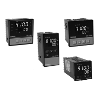
Guide to selecting the correct model and options based on part numbers.
Information on accessories for connecting the controllers to communication networks.
Explanation of the programming port and how to operate the keypad for setup.
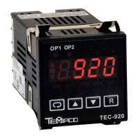
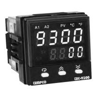
Description of the displays on the controller's front panel and character formats.
Instructions for unpacking the unit and mounting it into a panel.
Important safety and general guidelines for wiring the controller.
Diagrams showing lead termination and rear terminal connections for different models.
Guidelines for connecting power and installing sensors correctly.
Diagrams illustrating various methods for wiring control outputs.
Instructions for wiring alarm outputs to drive loads or contactors.
Configuration details for RS-485 and RS-232 serial communication.
Setting up security lockout levels and selecting signal input types.
Configuring settings for Output 1 and Output 2 control modes.
Explanation of alarm types, figures, and available operational modes.
How to select and arrange parameters for the user menu.
Configuration and operation of ramp and dwell timer functions.
Adjusting PV display and filtering unstable process values.
How the controller handles sensor breaks or A-D converter failures.
Step-by-step guide for automatic PID tuning.
Guidelines for manually adjusting PID parameters for optimal control.
Procedure for enabling and using manual control mode.
Configuring Modbus RTU protocol for data communication.
How to configure the controller to retransmit the process value.
Example application of controlling an oven with a dwell timer.
Example application of controlling a refrigerator below 0°C.
Example of an injection mold application using heat-cool control.
Step-by-step instructions for calibrating thermocouples, RTDs, and inputs.
Overview of Modbus functions (03, 06, 16) supported by the controllers.
Explanation of exception response codes for Modbus communication errors.
Mapping of controller parameters to Modbus register addresses.
Details on the product warranty terms and conditions.
Procedures for product returns and contact information for technical assistance.
Formulas for converting Modbus message data to actual parameter values.
List of error codes and recommended actions for troubleshooting.
| Display | Dual 4-digit LED |
|---|---|
| Power Supply | 100-240 VAC, 50/60 Hz |
| Display Digits | 4 |
| Mounting | Panel Mount |
| Control Mode | PID |
| Input Type | Thermocouple (J, K, T, E, R, S, B, N), RTD (PT100) |
| Output Type | Relay, 4-20mA |
| Temperature Range | Depends on sensor type (e.g., J: 0-760°C, K: -200-1370°C, PT100: -200-850°C) |
| Resolution | 0.1°C |