Do you have a question about the Tempco TEC-9300 and is the answer not in the manual?
Details the TEC-9300 controller's features, including self-tune fuzzy and PID capabilities.
Lists the unique, valuable, and advanced features of the TEC-9300 controller.
Explains the part numbering system based on hardware configuration options.
Describes the programming port and the function of DIP switches for setup.
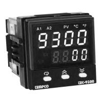
Details the front panel keypad operation and display elements.
Provides a flowchart of the controller's menu structure and parameter access.
Explains the different operating modes of the controller and their priorities.
Details parameters, their notation, format, description, range, and default values.
Provides essential precautions for safe and correct wiring of the controller.
Details how to connect the power supply to the controller.
Offers guidelines for proper sensor placement and installation for accurate measurements.
Explains the correct wiring procedures for thermocouple inputs.
Describes the wiring connections for RTD inputs.
Covers wiring for linear DC voltage and current inputs.
Details wiring for current transformer (CT) inputs for heater current monitoring.
Explains how to wire event input signals, including open collector and switch inputs.
Illustrates various wiring configurations for Output 1.
Shows different wiring options for Output 2.
Provides wiring diagrams for Alarm 1 and Alarm 2 relay outputs.
Details the wiring for RS-485 serial communication.
Explains the wiring setup for RS-232 serial communication.
Describes the wiring for analog retransmission signals.
Covers selection of sensor type, signal type, and unit for Input 1.
Details the selection of output signal types for Output 1 and Output 2.
Explains how to customize the user menu by selecting key parameters.
Describes setup for Heat Only ON-OFF, P (PD), and PID control modes.
Explains how to configure ON-OFF, P (PD), and PID control for cooling applications.
Explains how to configure alarm 1 or 2 as a dwell timer for delayed actions.
Covers setup and types of process alarms (normal, latching, holding).
Details deviation alarms that alert when the process deviates from the set point.
Explains deviation band alarms with high and low reference levels.
Explains loop break alarms for detecting sensor, controller, or switching device failures.
Covers sensor break alarms and their activation upon failure mode.
Explains how to confine the adjustment range for set point 1 (SP1).
Describes how to shift the controller display value from its actual value.
Explains the function of bumpless transfer for smooth control transitions.
Describes the self-tuning feature for optimizing PID parameters with minimal disturbance.
Explains the auto-tuning process for determining optimal PID values.
Details the available isolated DC power supplies for external transmitters or sensors.
Explains manual control mode for testing process characteristics or backup.
Describes how to select and view different process parameters in display mode.
Explains how to monitor heater current using Input 2 and a CT.
Provides a method to reload factory default parameter values.
Details the functions and wiring for the event input signal.
Explains how to use a second set point, often controlled by an event input.
Describes the use of dual PID sets for optimizing control across different process conditions.
Explains ramp functions for controlled temperature changes and dwell timers.
Details how to use external signals to control the set point.
Describes controlling one process based on the difference from another, e.g., water tank levels.
Explains how to limit output power to prevent excessive heating or cooling.
Covers RS-485 and RS-232 communication interfaces and setup.
Details analog output signals for retransmission of process values.
Explains the use of a digital filter to stabilize process value display.
Describes the sleep mode feature for reducing power consumption.
Details the pump control function for pressure regulation in systems.
Explains how to lock parameters using an external switch or DIP switch.
Details how to use the TEC-9300 for regulated water supply and pressure control.
Explains the advantages and application of VPFW SSR technology.
Describes a heat-only control application using a dwell timer for an oven.
Details a cool-only control application for a refrigerator.
Provides an example of PID heat-cool control for an injection mold.
Illustrates ramp and dwell functions for temperature cycling and baking oven applications.
Explains using remote set points for multi-zone ovens with synchronized temperature profiles.
Describes controlling one process based on the difference from another, e.g., water tank levels.
Details switching between PID sets for optimal control across varying process conditions.
Details the manual calibration steps for various input types and functions.
Provides general troubleshooting steps for common control problems and instrument issues.
Details supported Modbus functions (03, 06, 16) and their message formats.
| Display | Dual 4-digit LED |
|---|---|
| Power Supply | 100-240 VAC, 50/60 Hz or 24 VDC |
| Mounting | Panel mount |
| Control Mode | PID |
| Input Type | Thermocouple (J, K, T, E, R, S, B, N), RTD (PT100) |
| Output Type | Relay, SSR |
| Temperature Range | Depends on sensor type |
| Resolution | 0.1°C |