Do you have a question about the Tempur-Pedic ERGO and is the answer not in the manual?
Ensure all parts are accounted for before discarding packing materials; inspect base or boxes for components.
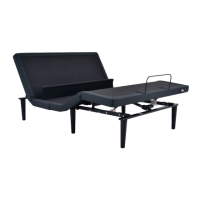
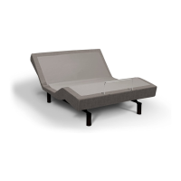
Position the base box in the desired location with the bottom facing up, removing binding straps and packing materials carefully.
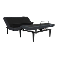
Thread legs with washers over bolts, ensuring recessed side faces the leg, and tighten by hand without over-tightening.
Refer to Owner's Manual for instructions on setting up and syncing two bases using the Smart Sync Cord and connecting strap.
Uncoil the input cord from the control box and plug it into the Power Supply unit.
Uncoil the power cord, connect it to the Power Supply, and position the supply on the ground with cords directed towards a surge protector.
With two people, carefully flip the base onto its legs, avoiding dragging or resting on its side to prevent damage.
Plug the base into a power source; use of a surge protector is strongly recommended.
Install AAA batteries in the remote control and test functions to verify proper setup before placing the mattress.
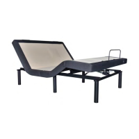
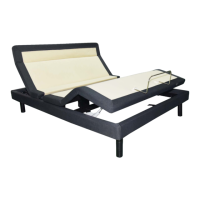
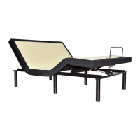
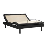
Slide the mattress retainer bar into the bracket on one side, then pull it to the opposite bracket and secure the other side.
Ensure all additional parts for King/Cal King setup are accounted for, checking base or boxes.
Align head and foot sections, ensuring bolt holes and frames match as shown in Fig. A and B.
Install 4 short bolts in the middle frame, securing them with nuts and washers as depicted in Fig. C and D.
Slide C-Clamps over frame connections and use long bolts, washers, and nuts to secure frames together using provided wrenches.
Attach legs by screwing them into leg threads on all four corners and diagonal sides in the middle, referencing Fig. G.
Connect foot motor and foot massage motor cables to labeled ports on the control box, and the LED cord to the main LED box.
| Type | Adjustable Bed Base |
|---|---|
| Wall-hugging Design | Yes |
| Warranty | 25-year limited warranty |
| Compatibility | Compatible with Tempur-Pedic mattresses and most other mattresses |
| Features | USB ports, under-bed lighting |
| Adjustability | Head and foot adjustability |
| Sizes | Queen, King, Split King |
| Preset Positions | Zero Gravity, Anti-Snore, Lounge, TV |
| Height | 15 inches (with legs) |
| Massage | Zone massage (on some models) |