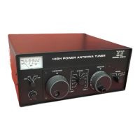
PILOT LAMP REPLACEMENT
The meter and dial scale lamps are all 14 volt, bayonet type, No. 1813 or 1892. Access to these
bulbs is by removing the top of the unit.
DIAL STRING REPLACEMENT
The dial string mechanism consists of two parts - a .020" diameter dacron non-stretchable string
and an elastic cord. The diameter of the dacron is important for proper pointer readout, since it is
wound on the inductor shaft and carries the pointer across the scale. Replace only with a string of the
same diameter. The elastic section provides string tension. Both are available from TEN-TEC. To
install, remove the top cover and unplug the meter plug from the switch board. Remove the knobs
and then the front panel. Tie a small loop in each end of the elastic cord such that the distance
between loops is 14". Similarly tie loops in each end of the dial string such that the total length
between loops is 46". Run the inductor to the full cw stop (roller to the rear) properly. Hook one loop
of the string over the left pulley shaft (not the pulley itself) on the pointer and place the pointer on
the top left edge of the subpanel. Run the string from the pointer over the left front pulley, back over
the pulley on the pointer, back over the left rear pulley, down the left edge of subpanel around the
corner standoff and finally under and around the inductor shaft where the end loop hooks over the
roll pin in the shaft. Hook one of the elastic loop ends over the lower left subpanel standoff, and run
the cord across the bottom edge, around the lower right standoff, over the top right pulley and hook
the loop end over the right hand pin on the pointer. This will now have the pointer tensioned.
Replace the front panel and inductor knob and turn the inductor to the full CCW stop. While holding
the inductor knobs, loosen the front set screw on the front inductor shaft coupler and turn the knob
until the pointer lines up with the zero on the dial scale then tighten the setscrew. Run the inductor
through its full range to see that the pointer has free travel and return to the zero point. Loosen the
inductor knob setscrew and position the zero mark on the knob skirt at top center and tighten the
setscrew. Replace the remaining knob making sure that 10 on the capacitor knob skirt coinsides with
full mesh position of the capacitor.
160 METER NOTE:
Some low impedances on 160 meters may require more capacitance than the 2400 pf available
with the capacitor at full mesh and S1 at position 5 on the LOW B side. Under such a condition, adding
an additional 1000 pf (.001 uf) 1 KV capacitor across the variable will usually produce a perfect match.
A low loss ceramic or mica transmitting capacitor should be used. If one cannot be obtained locally,
TEN-TEC will gladly supply one at no charge.
 Loading...