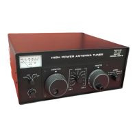
GENERAL
The model 229 antenna matching unit is an adjustable reactive network used for matching the
unbalanced 50 ohm output impedance of transmitters and transceivers to a variety of loads, either
balanced or unbalanced. It will perform this function over a frequency range of 1.8 to 30 Mhz.
Provision is made for selecting one of four antennas or for bypassing the matching network. A dual
range power and SWR meter is included.
SPECIFICATIONS
Circuit: Modified "L" network.
RF Power: 2KW.
Frequency Range: 1.8 to 30 Mhz.
Output Matching Range: At least 10:1 SWR, any phase angle, 1.8 to 30 Mhz. 3,000 ohms
maximum at full power.
Maximum Balanced Load (through the balun): 500 ohms.
Input Impedance: 50 ohms, nominal.
Capacitor Voltage Rating: 3.5KV.
Inductor: 18 uh silver plated roller inductor.
Finish: Dark painted front and rear, textured sides and top.
Size: HWD 5-1/2" x 13" x 11", overall.
Weight: 9 lbs.
INSTALLATION
1. Connect coaxial output of transmitter to coaxial input of tuner with short length of
RG-8 or RG-58 cable. Connectors are PL-259 type. Notice: To reduce possibility of RF
getting into transmitter, position tuner as far away from transmitter as is practical
especially when using open wire feedlines or long wire antenna.
2. Connect station ground buss to terminal on tuner marked GND with heavy metallic
braid or wire. This lead should go to the earth ground system with as short a lead as
possible.
3. Connect antenna transmission line(s) to appropriate terminals on the tuner as follows:
A. For coax fed antennas (unbalanced transmission lines), use either ANT 1,
ANT 2, ANT 3, or ANT 4.
B. For single wire antenna, connect to SINGLE WIRE terminal.
C. For balanced feedline systems, first install a jumper from SINGLE WIRE to one
BALANCED LINE terminal with a short wire. Then, connect feedline to the two
BALANCED LINE terminals.
In both single wire and balanced line systems, take special care to route transmission line
as far away from station equipment as possible. Never drape lines over transmitter.
These lines may have high voltage points inside the shack which present high rf fields.
 Loading...