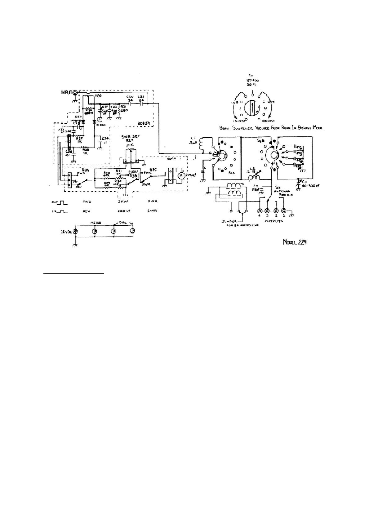
Figure 1
CIRCUIT DESCRIPTION
The matching circuit used in the model 229 is basically an "L" network. The "L" network has
several advantages over other circuit configuations. It has only two adjustable parts, one inductor
and one capacitor; most other networks use three. Because there are no internal nodes in the
network, the maximum circuit voltages and currents which occur are never are never more than those
present at the input or output terminals. Because there are only two variable components, there is
only one setting of each which will provide a perfect match to a given load impedance, and this
unique setting automatically provides the lowest network Q possible. Low Q means low circulating
currents, hence low loss, and it also provides the widest frequency bandwidth of operation before
retuning is necessary. Finally, since the inductor is always parallel, the network always provides a
two-pole lowpass response to provide harmonic rejection.
There are, however, some disadvantages which have prevented wider use of the "L" network in
the past. First, to match all possible antenna loads, two configurations are required. One, for
impedance greater than 50 ohms, requires the capacitor to be across the antenna. The other requires
the capacitor to be across the transmitter when the antenna impedance is less than 50 ohms. This
function is performed by switch S1. At high frequencies, as the load impedance approaches 50 ohms,
i.e. the antenna has a fairly low SWR already, the values of L and C in the network required for a
perfect match become very small -- smaller than the stray or minimum values of the components
used. To circumvent this problem, a small fixed compensating capacitor or inductor is placed into the
circuit depending on whether the network is configured for high or low impedance respectively (HI or
LOW on switch S1). At low frequencies, the value of network capacity needed to match some loads is