3
Then switch on receiver(s). The multiswitch will begin the process of auto-detecting which type(s) of receiver connected.
dSCR1 output is congured to connect only SCR/dSCR supported STBs. dSCR2/Legacy output is congured to connect
legacy STB (supports +13 V/+18V/22 kHz signals), but it switches to dynamic mode SCR/dSCR if receives a DiSEqC
command according EN50494/EN50607.
Set the highest frequency UB for STB located nearest to the multiswitch and lowest frequency for STB farthest to the
multiswitch. If you install less than max. possible STB’s use lowest frequencies rst.
Disconnect RF cable or STB from dSCR2/Legacy output to reset to Legacy / Start mode.
PIN code
All User Bands (UB) are protected by PIN Code to prevent the set of UB from being used / disturbed by another user
(see Table 2).
Default settings
1. SAT IF inputs are congured to use two Ku-band wideband LNBs (SAT A/B, LNB LO=10.40 GHz / 10.41 GHz. See label
on SRM522 multiswitch rear side and package).
2. dSCR1 output are congured to connect only SCR/dSCR supported STBs. All user bands are turn o (Start mode).
dSCR2/Legacy output is congured to connect legacy STB (supports +13 V/+18 V/22 kHz signals), but it switches to
Dynamic mode SCR/dSCR if receives a DiSEqC command according EN50494/EN50607. Output User Bands (UB) are
the same in both subscriber outputs (see Table 2).
3. PIN Codes (see Table 2 and see chapter "Conguration").
4. Only one UB plan is set depended of delivery region, if you need another plan (see chapter "Conguration" or contact
TERRA UAB).
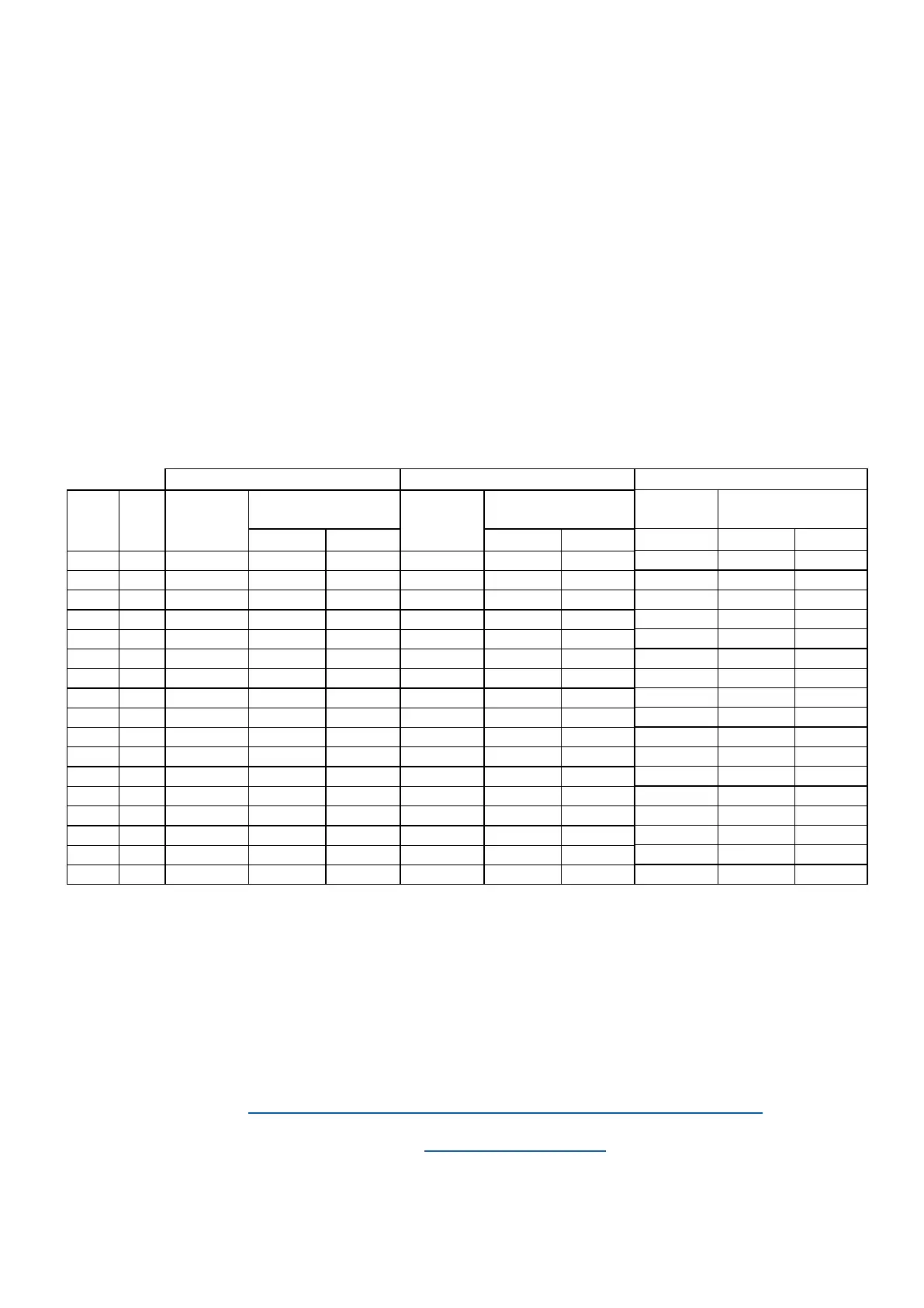
Marking: v.0 Marking: v.1
User
Band
(UB)
PIN
Code
Bandwidth,
MHz
Central frequency,
MHz
Bandwidth,
MHz
Central frequency,
MHz
EN50494 EN50607 EN50494 EN50607
UB0
UB1 1 40 1210 1210 40 1210 no
UB2 2 40 1420 1420 40 1420 no
UB3 3 40 1680 1680 40 1680 no
UB4 4 40 2040 2040 40 2040 no
UB5 5 40 1284 1284 40 no 985
UB6 6 40 1516 1516 40 no 1050
UB7 7 40 1632 1632 40 no 1115
UB8 8 40 1748 1748 40 no 1275
UB9 9 40 no 970 40 no 1340
UB10 10 40 no 1010 40 no 1485
UB11 11 40 no 1050 40 no 1550
UB12 12 40 no 1090 40 no 1615
UB13 13 40 no 1130 40 no 1745
UB14 14 40 no 1170 40 no 1810
UB15 15 40 no 1330 40 no 1875
UB16 16 40 no 1370 40 no 1940
Marking: v.2
Bandwidth,
MHz
Central frequency,
MHz
EN50494 EN50607
46 1210 1210
46 1420 1420
46 1680 1680
46 2040 2040
46 1006 1006
46 1057 1057
46 1108 1108
46 1159 1159
46 no 1261
46 no 1312
46 no 1363
46 no 1471
46 no 1522
46 no 1573
46 no 1624
46 no 1731
Table 2
Conguration
SRM522 conguration from Ku-band wideband LNB IF frequency range input mode to Ku band Quattro LNB IF frequency
range input mode (SAT A, LNB LOlow=9750 MHz and LOhigh=10600 MHz) can be changed connecting supplied 75Ω load
on conguration input (see Figure 1, pos. 15) before power turn on.
The other default settings of the device can be changed using dedicated programmer and software.
This multiswitch can be congured:
1. Up to 32 User Bands (UB) per pair outputs for use with STB’s supporting DiSEqC commands according to standards
EN50494/EN50607 (SCR/dSCR) as well as Legacy (+13 V/+18 V/22 kHz) commands.
2. Default settings Dynamic mode can be changed to Static mode.
3. Default setting Satellite A/B can be changed to C/D
(see Application diagrams http://www.terraelectronics.com/Pub/default.aspx?Page=products&PID=609) for installation
4 wideband LNBs (SAT B in the case Quattro LNB IF frequency range input mode).
PC Windows software can be free downloaded from www.terraelectronics.com.
Output conguration must be the same per pair of outputs. Pay attention to the numbering of outputs.
Some possible outputs pair congurations shown in Table 3:
 Loading...