Chapter 7 – Maintenance
Page 7-6 TestEquity 106 & 107 Temperature Chamber
Theory of Operation
Overview
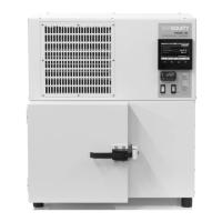
The chamber is heated by a nichrome heater. Cooling is accomplished by a single-stage
refrigeration system. The air is circulated by a propeller fan. The heater, evaporator, and fan are
located within an air plenum, which is on the back wall of the chamber interior.
Refer to the electrical and refrigeration drawings to identify the items referenced below.
Heating System
The chamber is heated by an open-element nichrome heater (HT1). The heater is located in the
air plenum. The temperature controller provides a time-proportioned output to a solid state relay
(SSR1). This turns the heater on/off as required to maintain the temperature set point.
A fusible heat limiter (HL) provides failsafe protection against a catastrophic failure by opening
the heater circuit at +192°C.
Refrigeration System
Cooling is accomplished by a single-stage refrigeration system. The refrigeration system
provides cooling to the chamber interior through a finned evaporator coil, which is located in the
air plenum.
The system uses refrigerant R-410A. High pressure liquid refrigerant is fed from the condenser
through the filter-drier, then solenoid valve, to the capillary tube. The capillary tube feeds the
finned evaporator coil, which is located in the air plenum where heat is absorbed to provide
cooling within the chamber. The reduction of pressure on the liquid refrigerant causes it to boil
or vaporize, absorbing heat which provides a cooling effect. The refrigerant vapor travels
through the suction line accumulator to the compressor suction inlet. The compressor takes the
low pressure vapor and compresses it, increasing both the pressure and the temperature. The hot,
high pressure vapor exits the compressor discharge valve and into the condenser. As the high
pressure vapor passes through the condenser, it is cooled by a fan, which blows ambient air
across the finned condenser surface. The vapor condenses into a liquid and the cycle is repeated.
The temperature controller’s cool output cycles the liquid-line solenoid valve (SV1) ON/OFF to
control the chamber temperature. When SV1 is ON, liquid refrigerant flows through the capillary
tube to the evaporator, providing full-capacity cooling. When SV1 is OFF, liquid refrigerant flow
is stopped, causing cooling to stop while the compressor remains ON. In this mode, the hot gas
regulator (HGR1) keeps the suction pressure above 5 PSIG.
During a high temperature cool-down or when SV1 is cycled OFF, it is possible for excessive
hot gas to return to the compressor. The suction line cooling thermostatic expansion valve
(TEV1) senses the suction line temperature and injects liquid refrigerant to cool the hot gas
within safe limits.
At chamber temperatures below –35°C, the temperature controller’s Alarm 2 disables the suction
cooling expansion valve and hot-gas bypass valve through SV2, while locking SV1 ON
regardless of the controller’s cool output status.