13
UK
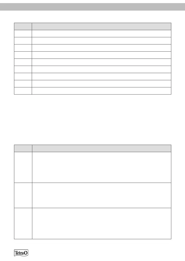
Tube system elements
Fig. B Description
1 Hose (2 pcs)
2 Attachment clip with suction cup (6 pcs)
3 U-piece inlet
4 Telescopic tube
5 Suction sieve
6 Foam pre-filter
7 U-piece outlet
8 Nozzle tube
9 Nozzle end tube (with sealing plug)
OPERATION
Switching on and o
The device is switched on when the plug is inserted into a socket. It is switched
o (no power) when the plug is pulled out.
Controls
Fig. C Description
1 Shut-o lever
Position up: Shut-o valve open. Water circulation on.
Position down: Shut-o valve closed. Water circulation o.
Position bottom right: The hose adapter is unlocked and can be
removed upwards.
2 Stopcocks
The flow rate can be adjusted using the IN stopcock (inlet). The
OUT stopcock (outlet) should always be fully open when the filter
is in use.
3 Start button
If there is no (or very little) water in the filter housing, the filter
pump cannot generate a flow of water. If you press the start button
several times, water is pumped into the filter housing and the filter
is vented.