8/19
55908014-17
INSTALLATION
Envelope containing operating instructions and
Declaration of Conformity
Convert to ¾" drain if required.
Reducing flare nut 1/2” – 3/8”
Fit to liquid connection on the CXE 70 indoor unit
when matched with a CKC 60 outdoor unit
The unit may be mounted on a wall or solid ceiling using brackets supplied. It should be matched with the appropriately
sized outdoor unit; this instruction should be used in conjunction with the outdoor unit installation instructions.
UNIT COMBINATIONS
1. Fit all kits prior to installing the unit. (Heater kit is easier to fit when unit has been mounted).
2. Ensure that the mounting surface will support the operating weight of the unit (see table below).
3. Mark out the mounting positions and drill holes to suit 6mm rawlbolt shields or equivalent strength fasteners
(ensure that the unit is positioned to give sufficient access (min 0.5m) to the removable side panel).
4. Fix the mounting brackets to the unit in the correct position for wall or ceiling mounting.
5. Raise the unit into position and secure the fixings, ensuring that it is square and level.
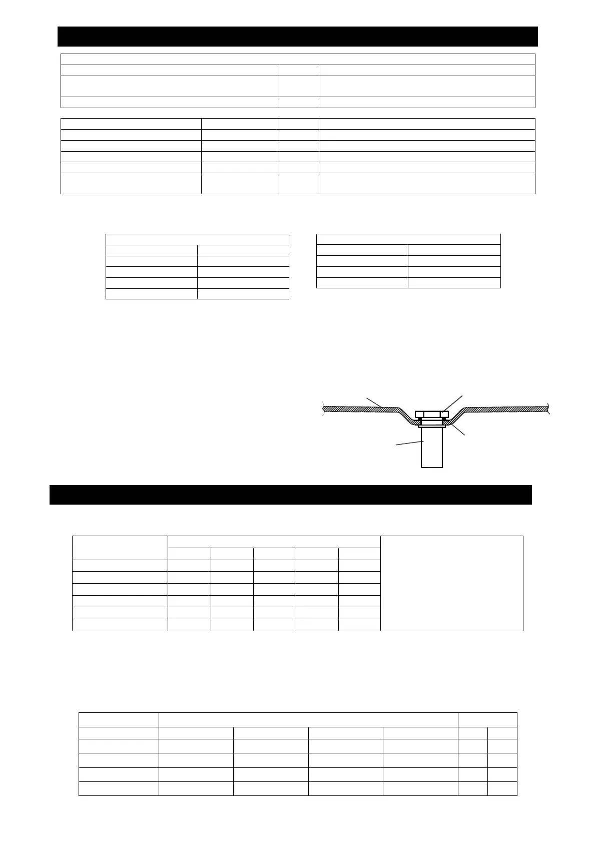
6. Remove the drain tray then fit the drain stub, nut &
gasket. Refit the drain tray.
NITROGEN CHARGE
The unit contains a small charge of dry nitrogen, which should
be discharged into the atmosphere. This is a non-toxic, non-
ozone depleting gas with no global warming potential.
FITTING LOSSES, in equivalent straight lengths of pipe (m).
To calculate the total equivalent
length, the equivalent lengths of all
fittings in a pipe run must be added
to the actual length of pipe in the
run: these are the fittings most
likely to be used.
R = Radius of bend
d = Diameter of tube
C = Centres of bend
A. USING SUCTION AND LIQUID LINES:
With the expansion device connected to the indoor unit, the equivalent pipe run should be 20m maximum,
including a maximum lift of 7.5m. Fully insulate the suction line. Ensure the suction pipe is insulated well over
the drain tray at the indoor unit. Liquid lines should be routed to avoid hot areas. This prevents flash gas
forming, which may result in erratic control of liquid refrigerant to the evaporator.
MAXIMUM EQUIVALENT LENGTH OF SUCTION LINE PIPE SIZES (m)
Minimum Set Temperature 4°C
Minimum Set Temperature 8°C
DRAIN TRAY
GASKET
NUT
DRAIN STUB
 Loading...