13/19
55908014-17
5. Run the system for a few minutes to allow it to stabilize. Where possible, charge to a sweat line on the
evaporator. Typical suction pressure on short lines at UK conditions should be approx. 3.8bar (55 psig).
6. Head pressure controller
The head pressure controller is factory set to suit the refrigerant. It may be necessary to adjust this to
suit site conditions, to raise or lower the nominal head pressure.
a. With the system switched off, connect a high pressure gauge to the liquid line service valve.
b. Switch on the system, and run for a few minutes to stabilise.
c. The head pressure should be approximately:
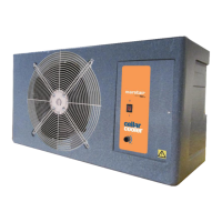
R407C: 275-280 psig (18.9-19.6barg) to achieve this remove sealing plug and insert 2mm or 5/64” allen key
into setting screw. Turn allen key clockwise (+) or counter clockwise (-) to readjust the setting. Do not turn
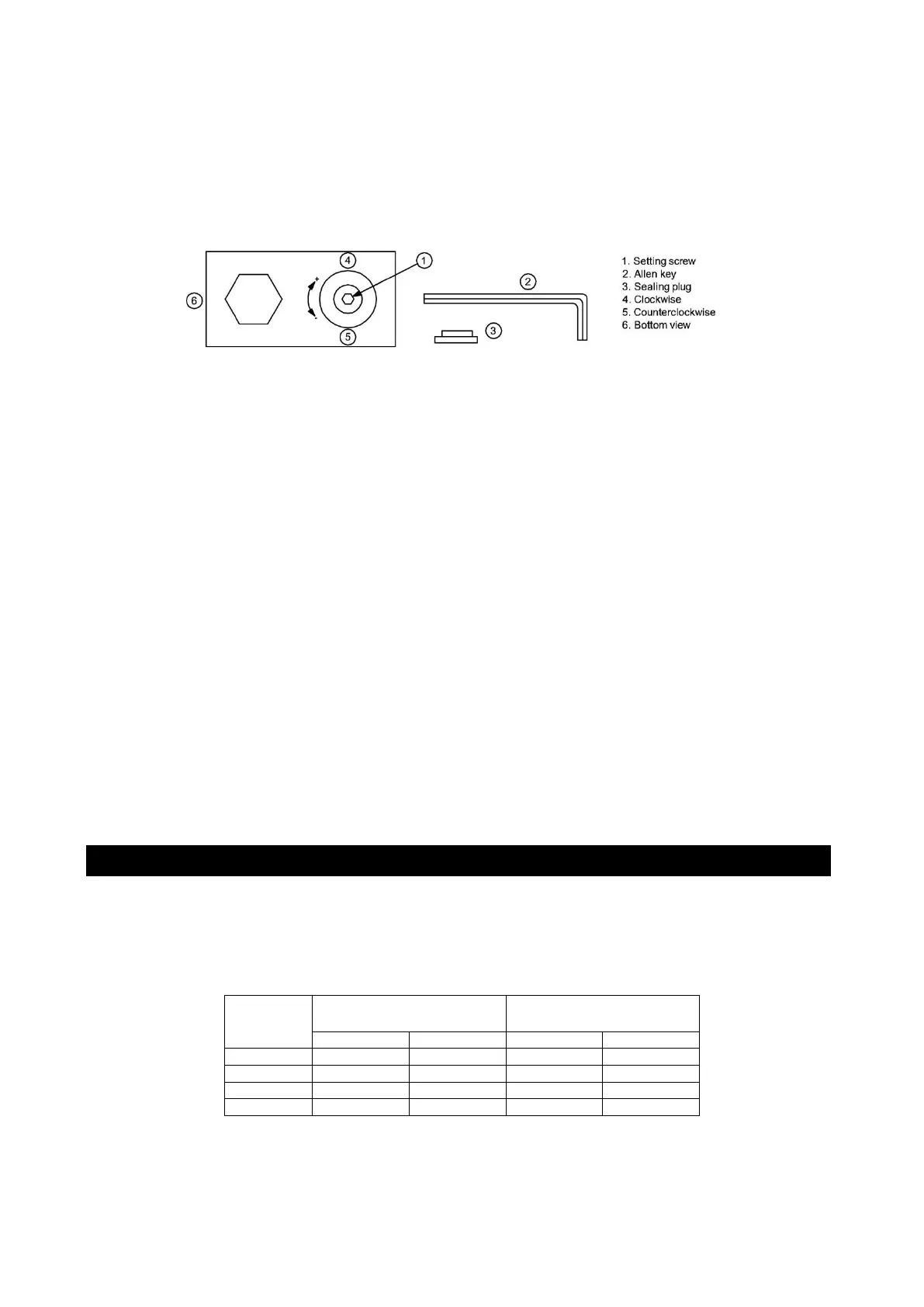
setting screw more than 3 turns clockwise (+3). Use following table as a quick guideline for setting:
After adjustment, re-insert sealing plug and make sure that it is properly fitted. IP65 protection requires
firmly sealed plug
NOTES:
Tolerances for condensing temperatures setpoint: ±2K
Min fan speed (0 rpm) and fan cut in pressure 200 psig (13.8 barg) are factory set and not adjustable.
NOTE: The condenser fan may stop if the operating pressure drops below 200 psig (13.8 barg)
ELECTRICAL CONNECTIONS
Cables are routed to the terminal block via the cable cord grips at the rear of the unit and then through the back of
the electrics box (see page 2).
Cables MUST be size compatible with the recommended system fuse.
FUSES
Note: On 3 ph systems the supply must go to the CKC outdoor unit and then to the CXE indoor unit.
 Loading...