~-------
~
945423-9701
A MODE key
is
also available on the keyboard and
is
intended to be used by terminal control pro-
grams
to
place the terminal
in
a specific operating mode. The way
in
which a specific keyboard
character set
is
selected
is
illustrated below:
SHIFT
CONTROL
UPPERCASE
LATIN
ARABIC
CHARACTER
SET
up
up up
down
up Lowercase Latin
up
up down
down
up Uppercase Latin
down
up
*
down
up Shifted Latin
up
up
*
up
down
Arabic
down
up
*
up
down
Shifted Arabic
*
down *
*
*
Control
*Don't care.
The keyboard character sets are illustrated
in
figures
G-2
through G-S.
G.3 DISPLAY UNIT
The Model
911
terminal provides a 305-millimeter (l2-inch) diagonal, high resolution display. The
screen can display 24,
SO-character lines
of
data: a total
of
1920
characters per screen. Three types
of
dot matrix are provided by the terminal: a
5x7
matrix that
is
used for Latin characters, a
7xS
for
smaller Arabic characters, and a 7xlO dot matrix for the more intricate Arabic characters. All
characters fit into a single character position on the screen.
G.4 DEVICE
SERVICE ROUTINE INTERFACES
In the Model
911
Arabic VDT, a special ROM
is
used that contains over
115
different character
shapes for the Arabic language alone. The shape displayed can be programmed to meet the
re-
quirements
of
the Arabic language itself. In general, a character has a different shape depending on
its position in the word: isolated, beginning, final, or medial. The appropriate shape provided in the
display
ROM
is
selected by the user's DSR according to the context
in
which a data character
is
entered. To map the keyboard data entered to the displayed data and to the user buffer, a user DSR
has to handle three interfaces: the keyboard/DSR interface, user buffer DSR interface, and the
display/DSR interface. Figure G-9
is
a simplified interface overview
of
the VDT controller. The
character tables used at each interface are designed to maximize the efficiency with which the
inter-
face can be handled. These character sets are listed
in
figures G-lO, G-11, and G-12.
11
12
13
29
30
31
32
33
34
49
50
51
52
53 54
69
70
71
72
73
74
87
88
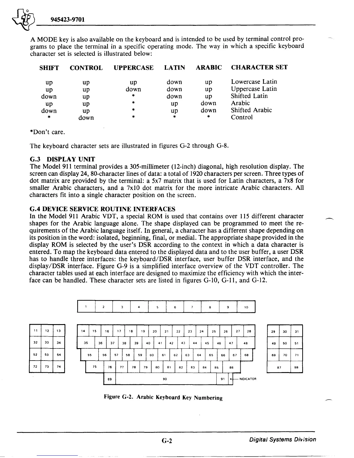
Figure G-2. Arabic Keyboard Key
Numbering
G-2
Digital Systems
Di~lsion

 Loading...
