User's Guide
SLAU443–May 2012
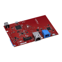
EEG Front-End Performance Demonstration Kit
This user's guide describes the characteristics, operation, and use of the ADS1299EEG-FE. This EVM is
an evaluation module for the ADS1299, an eight-channel, 24-bit, low-power; integrated analog front-end
(AFE) designed for electroencephalography (EEG) applications. The ADS1299ECG-FE is intended for
prototyping and evaluation. This user's guide includes a complete circuit description, schematic diagram,
and bill of materials.
The following related documents are available through the Texas Instruments web site at www.ti.com.
Device Literature Number
ADS1299 SBAS499
Contents
1 ADS1299EEG-FE Overview ............................................................................................... 4
1.1 Important Disclaimer Information ................................................................................ 4
1.2 Information about Cautions and Warnings ..................................................................... 4
2 Overview ..................................................................................................................... 5
2.1 Introduction ......................................................................................................... 5
2.2 Supported Features ................................................................................................ 5
2.3 Features Not Supported in Current Version .................................................................... 5
2.4 ADS1299EEG-FE Hardware ..................................................................................... 5
2.5 Factory Default Jumper Settings ................................................................................. 6
3 Software Installation ........................................................................................................ 7
3.1 Minimum Requirements ........................................................................................... 7
3.2 Installing the Software ............................................................................................. 7
3.3 Install the ADS1299 EVM Hardware Drivers ................................................................. 10
4 ADS1299EEG-FE Daughter Card Hardware Introduction ........................................................... 13
4.1 Power Supply ..................................................................................................... 14
4.2 Clock ............................................................................................................... 15
4.3 Reference .......................................................................................................... 16
4.4 Accessing ADS1299 Analog Signals .......................................................................... 16
4.5 Accessing ADS1299 Digital Signals ........................................................................... 16
4.6 Analog Inputs ..................................................................................................... 17
5 Using the Software: ADS1299 Control Registers and GUI .......................................................... 18
5.1 Overview and Features .......................................................................................... 18
5.2 Global Channel Registers ....................................................................................... 19
5.3 Channel Control Registers ...................................................................................... 19
5.4 GPIO and Other Registers ...................................................................................... 23
5.5 Lead-Off and BIAS Registers ................................................................................... 23
5.6 Register Map ...................................................................................................... 26
6 ADS1299EEG-FE Analysis Tools ....................................................................................... 27
6.1 Scope Tab ......................................................................................................... 27
6.2 Histogram Tool .................................................................................................... 28
6.3 FFT Tool ........................................................................................................... 29
7 EEG Specific Features .................................................................................................... 32
7.1 Reference Signal and Patient Bias Signal .................................................................... 32
SPI is a trademark of Motorola.
1
SLAU443–May 2012 EEG Front-End Performance Demonstration Kit
Submit Documentation Feedback
Copyright © 2012, Texas Instruments Incorporated