EasyManua.ls Logo

Texas Instruments ADS1256EVM-PDK User Manual

Texas Instruments ADS1256EVM-PDK
46 pages
To Next Page IconTo Next Page
Page #1 background imageLoading...
Page #1 background image
1
SBAU090ENovember 2003Revised November 2018
Submit Documentation Feedback
Copyright © 2003–2018, Texas Instruments Incorporated
ADS1256EVM and ADS1256EVM-PDK
User's Guide
SBAU090ENovember 2003Revised November 2018
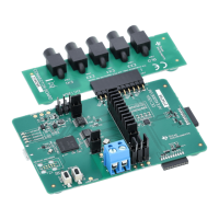
ADS1256EVM and ADS1256EVM-PDK
This user's guide describes the characteristics, operation, and use of the ADS1256EVM, both by itself and
as part of the ADS1256EVM-PDK. This EVM is an evaluation fixture for the ADS1256 24-bit delta-sigma
(ΔΣ) analog-to-digital converter (ADC). It also serves as an evaluation platform for the ADS1255, which is
a proper subset of the ADS1256. It allows evaluation of all aspects of the ADS1256 device. A complete
circuit description, schematic diagram, and bill of materials are included.
The following related documents are available through the Texas Instruments web site at www.ti.com.
Device Literature Number
ADS1256 SBAS288
REF5025 SBOS410
OPA350 SBOS099

Table of Contents

Question and Answer IconNeed help?

Do you have a question about the Texas Instruments ADS1256EVM-PDK and is the answer not in the manual?

Texas Instruments ADS1256EVM-PDK Specifications

General IconGeneral
CategoryMotherboard
ManufacturerTexas Instruments
Part NumberADS1256EVM-PDK
Tool is For Evaluation OfADS1256
Input Channels8
Data Rate30 kSPS
Power Supply5V
Sampling RateUp to 30 kSPS
Operating Temperature-40°C to +85°C
Product TypeEvaluation Module
ADC Resolution24 bits
Operating Voltage5V

Summary

Controls and Analog Interface

Power Supply Configuration

Power Supply Inputs

Details the power supply input connector and its configuration options.

Power Options and Voltage Selection

Jumper Block Configuration

Explains the jumper block for various power options and ground connections.

Digital Supply Voltage Selection

Details how to select the digital supply voltage (1.8V or 3.3V) using jumpers.

Voltage and Clock References

Clock Source Selection

EVM Operation

Analog Input Configuration

Details how analog input sources are applied and routed by switches S1 and S2.

EVM Operation Details

Default Settings

ADS1256EVM-PDK Kit Operation

Installing the ADCPro Software

Guides the user through installing the ADCPro software and EVM plug-in.

Setting Up the ADS1256EVM-PDK

Connecting the ADS1256EVM to the MMB0

Details the physical connection of the ADS1256EVM to the MMB0 motherboard.

Connecting the Power Supply

Running the Software and Completing Driver Installation

NI-VISA USB Device Driver Installation

Details the installation process for NI-VISA USB device drivers.

USBStyx Driver Installation

Guides through the installation of the USBStyx driver for device communication.

Performance Evaluation with ADCPro

Using the ADS1256EVM-PDK Plug-in

Details controlling ADS1256 settings and evaluating performance via the ADCPro plug-in.

Data Collection and Troubleshooting

Explains starting data collection and provides troubleshooting steps.

Related product manuals