www.ti.com
ADS1256EVM-PDK Kit Operation
21
SBAU090E–November 2003–Revised November 2018
Submit Documentation Feedback
Copyright © 2003–2018, Texas Instruments Incorporated
ADS1256EVM and ADS1256EVM-PDK
8.3.1.1 External Wall-Adapter Power-Supply Requirements
The external wall-adapter power-supply requirements are as follows:
• Output voltage: 6 VDC to 9 VDC
• Maximum output current: ≥ 500 mA
• Output connector: barrel plug (positive center), 2.0-mm I.D. × 5.5-mm O.D. (9-mm insertion depth)
NOTE: Use an external power supply that complies with applicable regional safety standards; for
example, UL, CSA, VDE, CCC, PSE, and so forth.
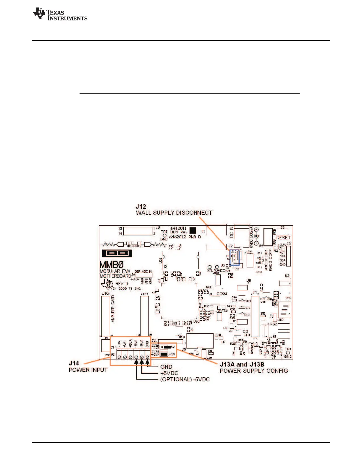
8.3.2 Connecting a Laboratory Power Supply
A laboratory power supply can be connected through terminal block J14 on the MMB0, as shown in
Figure 15. Both unipolar and bipolar configurations are supported.
To use a unipolar lab power supply configuration:
• Disconnect J12 on the MMB0.
• Connect a +5V dc supply to the +5VD terminal on J14.
• Connect ground of the dc supply to the GND terminal on J14.
For bipolar mode, also connect a –5V dc supply to the –5VA terminal on J14. It is not necessary to
connect a +5V dc supply voltage to the +5VA terminal on J14 if the +5V/+5VA position on J13 is shorted.
Figure 15. MMB0 Configured for Lab Power Supply