EVM Operation
www.ti.com
14
SBAU090E–November 2003–Revised November 2018
Submit Documentation Feedback
Copyright © 2003–2018, Texas Instruments Incorporated
ADS1256EVM and ADS1256EVM-PDK
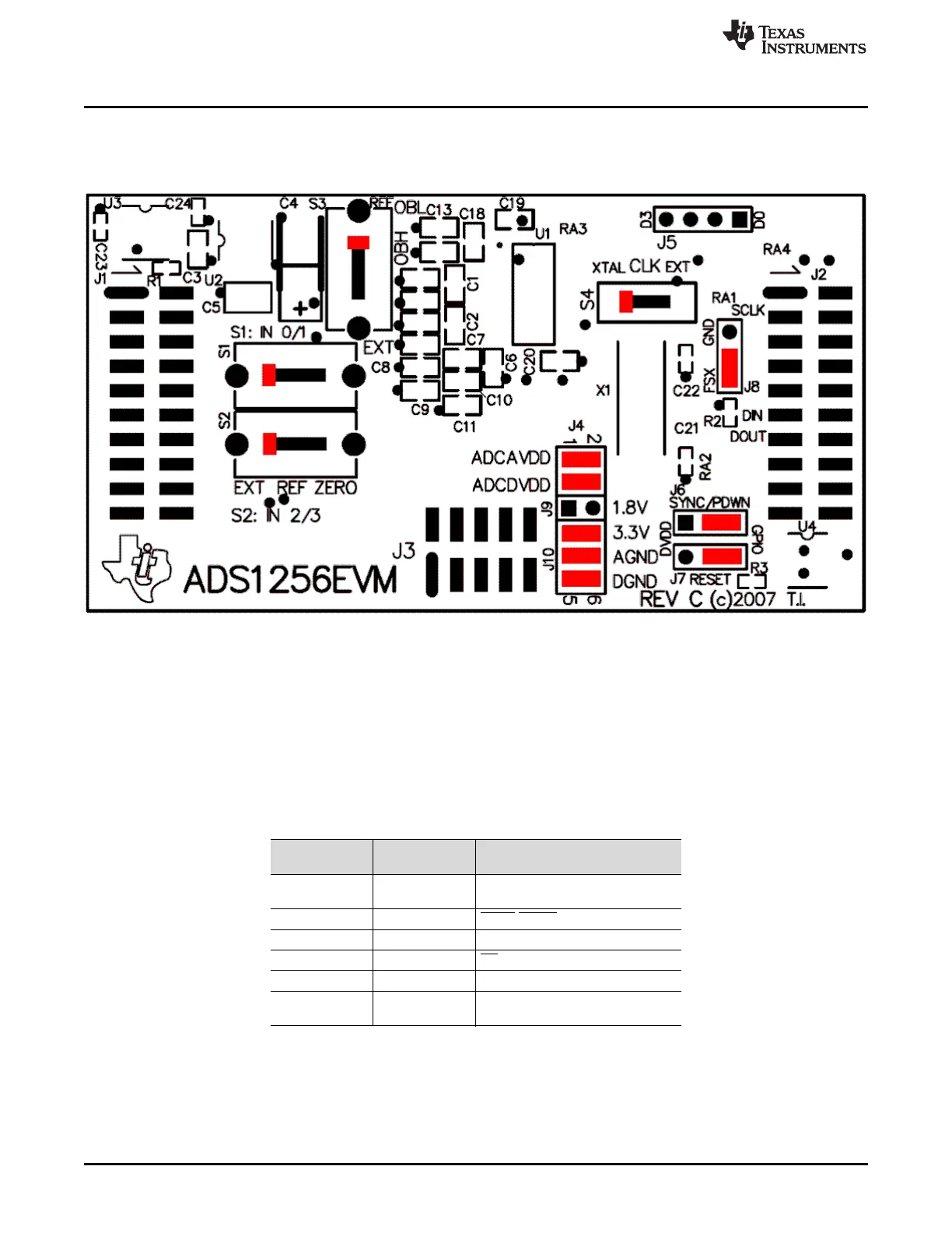
7.4 Default Jumper Settings and Switch Positions
Figure 7 shows the jumpers and switches found on the EVM and the respective factory default conditions
for each.
Figure 7. ADS1256EVM Default Jumper and Switch Locations
The jumpers on J4 provide a convenient way to measure the current for any of the power-supply currents
AVDD (analog +V power), DVDD (digital power), AVSS (analog –V power), or the ground connections
VGND and DGND. Simply remove the jumper for the appropriate power supply and use a current meter
between the jumper pins. The supply voltage for the digital supply (DVDD) can also be selected to be
either 1.8V or 3.3V; refer to Table 5.
Table 10 and Table 11 provide a list of jumpers and switches found on the EVM and the respective factory
default conditions for each.
Table 10. Default Jumper Positions
Jumper
Default
Jumpers Jumper Description
J4 1-2 and 3-4 AVDD and DVDD current
measurement connection
J6 2-3 SYNC/PDWN header connection
J7 1-2 RESET header connection
J8 1-2 CS header connection
J9 none +1.8VD connection
J10 1-2, 3-4, and 4-5 +3.3VD, AGND, and DGND
Cconnection