Do you have a question about the Texas Instruments Delfino TMS320F28379D and is the answer not in the manual?
Outlines the documentation and files provided with the Hardware Developer's Kit for evaluation and development.
Provides notes, warnings, and errata related to controlCARD revisions and general operation.
Details warnings and changes for different controlCARD revisions (R1.0a, R1.1, R1.1a, F28379D R1.3).
Highlights key features of the Delfino F28379D microcontroller and its capabilities.
Specifies the environmental conditions under which the kit is assumed to operate.
Explains how to power and configure the controlCARD for operation, including switch settings.
Guides on where to find example software projects for experimenting with the F28379D MCU.
Details the on-card emulation and USB-to-UART adapter functionality, including serial number considerations.
Describes the external connector J9 and its capabilities for connecting to other boards.
Provides guidelines for optimal performance of the on-chip ADCs, including input circuit design.
Details the various connectors available on the controlCARD for interfacing with other hardware.
Explains the function of jumpers for enabling/disabling specific features like USB PHY connection.
Describes the status LEDs and their corresponding functions or control signals.
Discusses the role of resistors and capacitors, particularly for ADC reference configuration.
Explains the function of switches for boot mode selection and ADC voltage reference control.
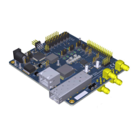
The Delfino F28379D controlCARD (TMDSCNCD28379D) from Texas Instruments (TI) serves as an excellent platform for learning and experimenting with the F2837x device family, which is part of TI's C2000™ family of microcontrollers (MCUs). This 180-pin controlCARD is engineered to offer a well-filtered and robust design, ensuring reliable operation in a wide range of environments. The document provides comprehensive hardware details of the F28379D controlCARD, explaining its various functions, the placement of jumpers, and the connectors available on the board.
The Delfino F28379D controlCARD is built around the Delfino F28379D Microcontroller, a high-performance C2000 microcontroller that forms the core of the controlCARD's functionality. It features an 180-pin HSEC8 Edge Card Interface, which ensures compatibility with all C2000's 180-pin controlCARD-based application kits and other controlCARDs. For compatibility with 100-pin controlCARDs, the TMDSADAP180TO100 adapter card (sold separately) can be used.
A key feature is the built-in Isolated JTAG Emulation, provided by an xds100v2 emulator. This offers a convenient interface to Code Composer Studio™ without the need for additional hardware. A switch allows users to easily toggle between using the on-board emulator and an external JTAG emulator.
The controlCARD also offers extensive connectivity options, including connectors for USB, a microSD card, and isolated UART/SCI with the F2837x MCU. A high-density connector is also available for experimenting with external memory. Most GPIO, ADC, and other critical signals are routed to hard gold connector fingers, ensuring robust connections. The power supply filtering is robust, with a single 5V input supply powering an on-CARD 3.3V LDO, and all MCU inputs are decoupled using LC filters near the device. ADC inputs are clamped by protection diodes, and anti-aliasing filters (small RC filters) can be easily added to several ADC input pins to reduce noise.
The F28379D controlCARD supports USB host/device connectivity via its micro-USB port, J8. However, it's important to note that this port is not isolated from the board ground. The controlCARD also provides emulation and USB-to-UART adapter functionality, enabling convenient debugging and demonstration of the F2837x MCU. The FTDI chip, its support circuitry, and associated isolation components are located in Macro A on the left section of the controlCARD. Each F28379D controlCARD's xds100v2 is programmed with a fixed serial number. If multiple controlCARDs are used in a debug session, some may need to be reprogrammed to have unique serial numbers.
To operate the controlCARD, the MCU must be powered, typically by supplying 5V through the HSEC connector via an accompanying baseboard, such as a docking station. In this scenario, 5VDC should be input into the docking station's J1 or J17, and SW1 should be toggled to the appropriate position. Alternatively, the MCU can be powered via the micro-USB connector on the controlCARD.
The configuration of switches on A:SW1 determines whether the on-board emulator is active, if an external emulator can be used, or if the device will boot from FLASH/peripherals. For example, in "Debug Using CCS and the On-Card xds100v2 Emulator" mode, A:SW1 (controlCARD) should be in Position 1: ON (up), and a mini USB cable should connect A:J1 to the computer. In CCS, the target configuration should be set to "TMS320F28379D device with an xds100v2 emulator." For "Debug Using CCS and an External Emulator via the Baseboard," A:SW1 (controlCARD) should be in Position 1: OFF (down), and an external emulator should be connected. For "Standalone (Boot from FLASH or other boot mode)," A:SW1 (controlCARD) should be in Position 1: OFF (down), and SW1 can be set as desired.
The external connector J9 allows connection to another board, providing access to EMIF2, SPI-C, I2C-A, and two GPIOs. However, care must be taken to avoid contention, especially with GPIOs 122-125, which also connect to the microSD connector, and GPIOs 53-68 (EMIF data lines) and 91-92 (I2C portions), which also go to the baseboard via the HSEC connector.
The controlCARD's on-chip ADCs are configurable 12-bit/16-bit architectures. For optimal performance, the input signal should be as precise as possible. It is recommended to use either Negative-Positive 0 PPM/°C (NPO) or Ceramic On Glass (COG) capacitors for better stability over temperature and across input frequencies.
The USB PHY connection enable/disable jumpers (J2-J7) control the connection between the MCU and the USB PHY. With all jumpers up, the MCU connects to the USB PHY via GPIOs 42, 43, 46, 47, 120, and 121. With all jumpers down, the MCU will not connect to the USB PHY, and all signals will instead go through the 180-pin controlCARD connector.
The controlCARD is designed to be robust, but certain considerations are important for long-term reliability. For instance, the micro-USB port J8 is not isolated from the board ground, so external USB isolation buffers may be required in high-power applications. In extreme cases where the board/controlCARD requires more power than a computer's USB port can provide (5V @ 500mA), an external 5V power supply (2.5 mm inner diameter x 5.5 mm outer diameter) plugged into J1 is recommended.
For the ADC voltage references, R51-R54 were mistakenly populated with 100 MΩ resistors instead of 100 mΩ resistors in some revisions. This can affect the accuracy and precision of ADC results. It is recommended to replace these with 100 mΩ, 0603, 5% tolerance (or better) resistors. For lab evaluation, shorting R51-R54 with 0 Ω resistors or solder bridges is acceptable, but populating with 100 mΩ is preferred.
The boot mode switch (SW1) controls the boot options of the F2837x device. Users can select between Parallel I/O, Boot from SCI, Wait Boot Mode, or Get Mode (Flash by default) by setting Switch Position 1 (GPIO-72) and Switch Position 2 (GPIO-84) accordingly.
The ADC VREFHI Control Switches (SW2 for modules A & B, SW3 for modules C & D) allow users to configure the ADC's voltage reference. In the left position, the ADC uses VDDA (3.3V) as its voltage reference, resulting in reduced accuracy/precision. In the right position, the ADC can use a precise 3.0V voltage reference or an external voltage, with R59 and R60 determining the specific setting. These switches provide flexibility in optimizing ADC performance based on application requirements.
The controlCARD includes LEDs (LD1, LD2, LD3) for status indication: LD1 turns green when the controlCARD is powered ON, while LD2 and LD3 are red and controlled by GPIO-31 and GPIO-34, respectively, with negative logic. These indicators aid in monitoring the device's operational status.
| Manufacturer | Texas Instruments |
|---|---|
| Series | Delfino |
| Model | TMS320F28379D |
| Core Size | 32-Bit |
| Clock Speed | 200 MHz |
| ADC Resolution | 12 bit |
| ADC Channels | 24 |
| Number of I/O | 169 |
| Peripherals | DMA, POR, PWM, WDT |
| Operating Temperature | -40°C ~ 125°C (TJ) |
| Core Processor | C28x |
| Flash Memory | 1MB (512KB per CPU) |
| Communication Interfaces | CAN, I2C, SCI, SPI, McBSP |
| Package / Case | LQFP |