Getting Familiar With the controlCARD
www.ti.com
4
SPRUI76A–March 2017–Revised January 2019
Submit Documentation Feedback
Copyright © 2017–2019, Texas Instruments Incorporated
Delfino™ TMS320F28379D controlCARD R1.3
• Connectivity – The controlCARD contains connectors that allow the user to experiment with USB, a
microSD card, and isolated UART/SCI with the F2837x MCU. A hi-density connector is also provided
to experiment with external memory.
• Key Signal Breakout – Most GPIO, ADC and other key signals routed to hard gold connector fingers.
• Robust Power Supply Filtering – Single 5 V input supply powers an on-CARD 3.3 V LDO. All MCU
inputs are then decoupled using LC filters near the device.
• ADC Clamping – ADC inputs are clamped by protection diodes.
• Anti-Aliasing Filters – Noise filters (small RC filters) can be easily added on several ADC input pins.
3.2 Assumed Operating Conditions
This kit is assumed to run at standard room conditions. The EVM should run at approximately standard
ambient temperature and pressure (SATP) with moderate-to-low humidity.
3.3 Using the controlCARD
In order for the controlCARD to work, the controlCARD’s MCU must be powered. This is most often done
by inputting 5 V through the HSEC connector via an accompanying baseboard. For example, if using a
docking station baseboard, 5VDC should be input into the docking station’s J1 or J17. Then, SW1 needs
to be toggled to the appropriate position.
Optionally, the MCU could also be powered via the micro-USB connector on the controlCARD.
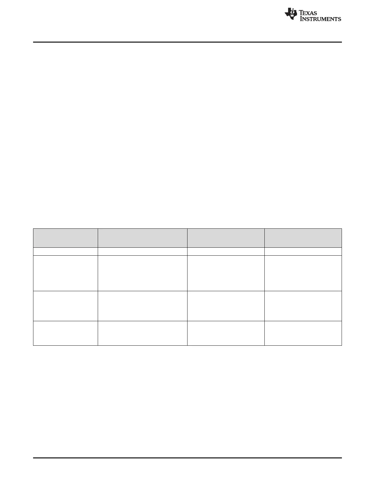
Based on the way the controlCARD will be used, additional hardware settings are necessary, see Table 1.
Table 1. Getting Started Reference
Debug Using CCS and the On-Card
xds100v2 Emulator
Debug Using CCS and an
External Emulator via the
Baseboard
Standalone
(Boot from FLASH or other
boot mode)
A:SW1 (controlCARD) Position 1: ON (up) Position 1: OFF (down) Position 1: OFF (down)
A:J1 (controlCARD) Connect a mini USB cable between
A:J1 and your computer.
--- ---
In CCS, use this target configuration:
TMS320F28379D device with an
xds100v2 emulator.
SW1 (controlCARD) Position 1: OFF (up)
Position 2: ON (down)
Putting the C2000 device into Wait
Mode can reduce the risk of
connectivity issues.
Position 1: OFF (up)
Position 2: ON (down)
Putting the C2000 device into
Wait Mode can reduce the risk of
connectivity issues.
Set SW1 as desired
Baseboard’s JTAG
connector
(J2 on the Docking Station
baseboard)
--- Connect an external emulator. ---
Code Composer Studio is an Integrated Development Environment (IDE) used to debug and develop
software for the C2000 series of MCUs.
CCS can be downloaded from the following URL: http://processors.wiki.ti.com/index.php/Download_CCS.
For users new to C2000’s F28x7x series of devices and CCS, TI’s Technical Training Organization
provides several workshops (online and in person) that may be helpful:
• http://processors.wiki.ti.com/index.php/C2000_32-bit_Real-Time_MCU_Training
• http://processors.wiki.ti.com/index.php/Hands-On_Training_for_TI_Embedded_Processors
The following PDF documents are provided to describe where each of the F2837x MCU’s pins will appear
on the controlCARD connector/docking station:
• TTMDSCNCD28379D_180cCARD_pinout_R1_3 – tells where each MCU pin will go on the HSEC
controlCARD connector or the 120/180-pin controlCARD docking station.

 Loading...


