EasyManua.ls Logo

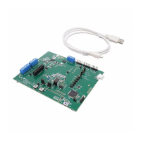
Texas Instruments TPS25751EVM

Texas Instruments TPS25751EVM
56 pages
To Next Page IconTo Next Page
Loading...
EVM User's Guide: TPS25751EVM
TPS25751 Evaluation Module
Description
The TPS25751 is a highly integrated stand-alone USB
Type-C
®
and Power Delivery (PD) controller optimized
for applications supporting USB-C PD Power. The
TPS25751 integrates managed power paths with
robust protection for a complete USB-C PD design.
The TPS25751 also integrates control for external
battery charger ICs for added ease of use and
reduced time to market. The intuitive web based
GUI asks the user a few simple questions on the
application's needs using clear block diagrams and
simple multiple-choice questions. The GUI creates
the configuration image for the user's application,
reducing much of the complexity associated with
competitive USB-PD designs.
Get Started
1. Order the TPS25751EVM, highly integrated USB
Type-C and USB PD Controller evaluation module
2. Read the TPS25751EVM user's guide
3. Start development with the Application
Customization Tool
4. Refer to the data sheet, technical reference
manual, or E2E for questions and support
Features
TPS25751 is certified by USB-IF for PD3.1
specification (TID# 10306)
Up to 100W (20V/5A) source and sink applications
with integrated I2C control for TI battery chargers
BQ25756, BQ25756E, BQ25792, BQ25798,
and BQ25713
100W (20V/5A) source and 100W (20V/5A)
sink with BQ25756(E)EVM for 1S-14(7)S
battery applications
45W (20V/2.25A) source and 60W (20V/3A)
sink with BQ25792/8EVM for 1S-4S battery
applications
60W (20V/3A) source and 60W (20V/3A)
sink with BQ25713EVM for 1S-4S battery
applications
Easy-to-use GUI with pre-configured firmware to
configure:
Programmable Power Supply (PPS) within
5V-21V range
Liquid Detection and Corrosion Mitigation
measureable on SBU1 and SBU2
Multiple test points and headers for quick and easy
debug
Exposed VBUS and CCx test points to monitor
PD traffic
PP5V and PPHV test points to measure voltage
transitions
Applications
Battery pack for cordless power tool, power bank,
retail automation and payment
Wireless speakers, cordless vacuum cleaner
Personal/portable electronics, industrial
applications
Medical applications, personal care and fitness
TPS25751EVM
www.ti.com Description
SLVUCP9A – NOVEMBER 2023 – REVISED MARCH 2024
Submit Document Feedback
TPS25751 Evaluation Module 1
Copyright © 2024 Texas Instruments Incorporated

Table of Contents

Question and Answer IconNeed help?

Do you have a question about the Texas Instruments TPS25751EVM and is the answer not in the manual?

Texas Instruments TPS25751EVM Specifications

General IconGeneral
BrandTexas Instruments
ModelTPS25751EVM
CategoryMotherboard
LanguageEnglish

Summary

Evaluation Module Overview

1.1 Introduction

Provides an overview of the TPS25751 Evaluation Module and its purpose.

1.2 Kit Contents

Lists the components included in the TPS25751EVM kit.

1.3 Specification

References the block diagram of the EVM.

1.4 Device Information

Details the TPS25751D and TPS25751S PD controllers on the EVM.

Hardware

2.1 Power Requirements

Explains how to power the TPS25751EVM via Type-C or bench supply.

2.2 Setup

Describes the default EVM configuration and initial setup steps.

2.3 Header Information

Details the pinout and function of the J6 header.

2.4 Jumper Information

Explains the function and location of jumpers on the EVM.

2.5 LED Information

Lists the LEDs on the EVM and their meanings.

2.6 Test Points

Identifies key test points on the EVM for measurements.

2.7 Switches and Buttons

Describes the function of switches and push buttons.

Software

3.1 Software Description

Details the software available for TPS25751 configuration and its installation.

3.2 Software Development

Outlines the capabilities of the Application Customization Tool.

3.3 Using the Application Customization Tool

Guides on using the GUI tool for configuration and flashing.

Application Specific Use Case

4.1 Application Specific General Overview

Overview of setting up battery charging and Liquid Detection/Corrosion Mitigation.

4.2 TPS25751 EVM and BQ257 xxEVM Setup

Guides on integrating TPS25751EVM with BQ charger EVMs.

4.3 Liquid Detection and Corrosion Mitigation Overview

Explains the Liquid Detection and Corrosion Mitigation feature of the EVM.

Hardware Design Files

5.1 Schematics

Presents schematic diagrams for key EVM components.

5.2 PCB Layouts

Shows composite views of the EVM's PCB layers.

5.3 Bill of Materials (BOM)

Lists all components used in the TPS25751EVM.

Additional Information

6.1 Trademarks

Lists trademarks used in the document and their owners.

6.2 Electrostatic Discharge Caution

Warns about potential damage from ESD and proper handling.

6.3 Terminology

Refers to glossaries for terms and definitions.

6.4 Device Support

Provides disclaimers for third-party products and firmware updates.

6.5 Documentation Support

Lists resources for obtaining additional documentation.

6.6 Receiving Notification of Documentation Updates

Explains how to subscribe for documentation updates.

6.7 Support Resources

Points to TI E2E™ forums for support and answers.

Revision History

Changes from Revision * (November 2023) to Revision A (March 2024)

Details the changes made in the latest revision of the document.

Related product manuals