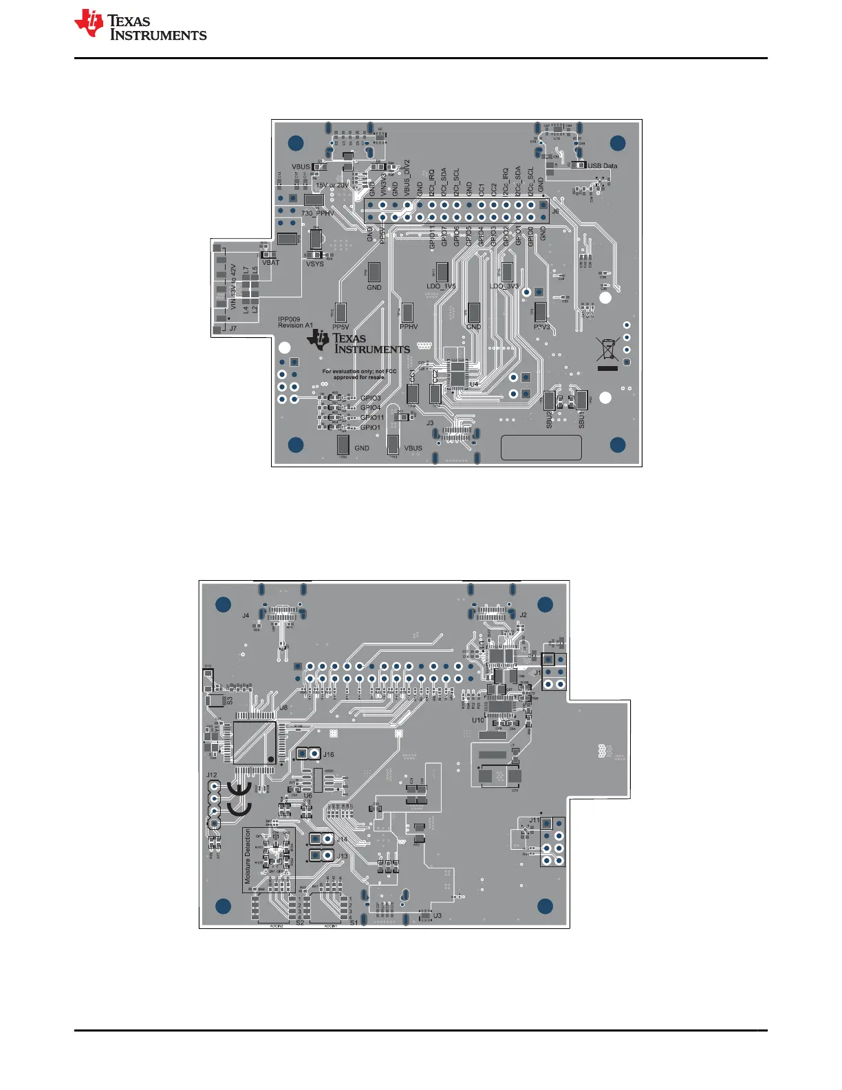
Home
Texas Instruments
Motherboard
TPS25751EVM
Texas Instruments TPS25751EVM User Manual
5
of 1
of 1 rating
56 pages
Give review
Manual
Specs
To Next Page
To Next Page
To Previous Page
To Previous Page
Loading...
5.2 PCB Layouts
Figure 5-7. TPS25751EVM T
op Layer Composite View
Figure 5-8. TPS25751EVM Bottom Layer Composite View
www
.ti.com
Hardware Design Files
SL
VUCP9A – NOVEMBER 2023 – REVISED MARCH 2024
Submit Document Feedback
TPS25751 Evaluation Module
39
Copyright © 2024 T
exas Instruments Incorporated
38
40
Table of Contents
Description
1
Get Started
1
Table of Contents
2
Features
1
Applications
1
1 Evaluation Module Overview
4
Introduction
4
Kit Contents
4
Specification
4
Device Information
4
Figure 1-1. TPS25751EVM Block Level Diagram
4
Table 1-1. Devices on TPS25751EVM
4
2 Hardware
5
Power Requirements
5
Setup
5
Header Information
5
Figure 2-1. J6 Header
5
Table 2-1. J6 Header Pinout
6
Jumper Information
7
Figure 2-2. Jumper Locations
7
Table 2-2. Jumper Descriptions
7
LED Information
8
Test Points
8
Switches/Push Buttons
8
Table 2-3. Leds
8
Table 2-4. Test Points
8
Table 2-5. Switches/Push Buttons
8
3 Software
9
Software Description
9
Figure 3-1. Application Customization Tool Download
9
Software Development
10
Using the TPS25751 Application Customization Tool
10
Figure 3-2. Application Customization Tool Configuration
11
Table 3-1. TPS25751 Configuration
11
Figure 3-3. Enabling Advanced Configuration
14
Figure 3-4. Using Advanced Configuration
14
Figure 3-5. TPS25751EVM Connection with PC
15
Figure 3-6. Serial Port Configuration Settings
16
Figure 3-7. Flash to Device from Current Configuration
16
Figure 3-8. Flash to Device from Current Configuration
17
Figure 3-9. Flash to Device from Current Configuration
17
Figure 3-10. Resetting Configuration
18
Figure 3-11. Export Settings in Application Customization Tool
19
Figure 3-12. Import Settings in Application Customization Tool
20
Figure 3-13. Generating Binary Configuration Using the Application Customization Tool
21
4 Application Specific Use Case
23
Application Specific General Overview
23
TPS25751EVM and Bq257Xxevm Setup
23
Figure 4-1. J1 Jumper for BQ Setups
23
Figure 4-2. Ribbon Cable Connection to J11
24
Figure 4-3. TPS25751EVM and BQ25756(E)EVM Hardware
24
Figure 4-4. TPS25751EVM and BQ25792/8EVM Hardware
26
Table 4-1. TPS25751EVM and BQ25792/8EVM Connections
26
Table 4-2. TPS25751EVM and BQ25713EVM Connections
28
Liquid Detection and Corrosion Mitigation Overview
30
Table 4-3. Liquid Detection Test Points
32
Table 4-4. Liquid Detection/Corrosion Mitigation Default Configuration
32
5 Hardware Design Files
33
Schematics
33
PCB Layouts
39
Bill of Materials (BOM)
43
Table 5-1. Bill of Materials
43
6 Additional Information
49
Trademarks
49
Electrostatic Discharge Caution
49
Terminology
49
Device Support
49
Documentation Support
49
Receiving Notification of Documentation Updates
50
Support Resources
50
7 Revision History
50
5
Based on 1 rating
Ask a question
Give review
Questions and Answers:
Need help?
Do you have a question about the Texas Instruments TPS25751EVM and is the answer not in the manual?
Ask a question
Texas Instruments TPS25751EVM Specifications
General
Brand
Texas Instruments
Model
TPS25751EVM
Category
Motherboard
Language
English
Related product manuals
Texas Instruments TPS65994 EVM
59 pages
Texas Instruments TPS7H5001-SP
20 pages
Texas Instruments TM4C Series
36 pages
Texas Instruments EK-TM4C123GXL
27 pages
Texas Instruments Tiva TM4C1294
34 pages
Delfino TMS320F28379D
17 pages
Texas Instruments J721E
84 pages
Texas Instruments LMK04828
113 pages
Texas Instruments BQ79600-Q1
25 pages
Texas Instruments ADS1256EVM-PDK
46 pages
Texas Instruments bq34110EVM-796
24 pages
LAUNCHXL-F28377S
22 pages