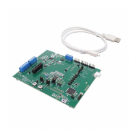
2.4 Jumper Information
Figure 2-2. Jumper Locations
Table 2-2. Jumper Descriptions
Jumper Designator Description
J1 Power selector between VBAT and 730_PPHV to board system power (VSYS), refer to Figure 4-1.
J13 3.3V input to VIN_3V3 on TPS25751. Remove jumper to disconnect 3.3V power to TPS25751 to simulate
dead-battery mode.
J14 3.3V output from LDO_3V3 on TPS25751. Remove jumper to disconnect 3.3V power to the on-board
EEPROM. This also disconnect 3.3V pull-up on the I2Cc and I2Ct lines.
J16 I2Cc data line between TPS25751 and EEPROM, remove jumper to disable I2C flash.
www.ti.com Hardware
SLVUCP9A – NOVEMBER 2023 – REVISED MARCH 2024
Submit Document Feedback
TPS25751 Evaluation Module 7
Copyright © 2024 Texas Instruments Incorporated
 Loading...


