Table 1-1. Devices on TPS25751EVM (continued)
Designator Device Name Description
U8 TM4C123GH6PM TIVA MCU, used in conjunction with GUI to flash the EVM
U9, U11 TLV75533 Low-dropout voltage regulator for 3.3V (P3V3)
U10 LM76005 Synchronous step-down converter for 5V (PP5V)
2 Hardware
2.1 Power Requirements
For standalone PD evaluation, the main power supply for the TPS25751EVM is through the Type-C Sink only
port (J2), which accepts 45W Type-C PD Source (15V to 20V). If the Type-C adapter is not capable of minimum
15V, then the TPS25751EVM does not power on properly. Alternatively, the EVM can also be powered on from
an external bench supply connected to VSYS test point (TP19), with the bench supply providing 15V-20V range.
Note
VSYS (TP4) has an absolute maximum rating of 48V with recommended maximum of 42V. Applying
more than the maximum voltage can cause damage to the EVM.
The TPS25751EVM can also be powered directly through Type-C Connector (J3) to simulate the TPS25751 in
a dead battery scenario. When the TPS25751EVM is powered only through port J3, the EVM acts as sink only
(unable to source unless VSYS is powered on).
For battery charging application, the selected BQ EVM can be used to power on the TPS25751EVM. The
BQ25756EVM comes with a interfacing connector to connect to J7 connector on the TPS25751EVM. If a BQ
Battery Charger is connected, the VBUS side of the BQ Battery Charger is connected to the internal high-voltage
bidirectional power path (PPHV) of the TPS25751EVM. For more information on setting up and programming
TPS25751 for battery charger application refer to Section 4.2.
2.2 Setup
Out of the box, the TPS25751EVM is configured for 15W (5V/3A) source and 100W (20V/5A) sink power.
When different configurations are required, use the Application Customization Tool to create a configuration
or load a different configuration template. Refer to Section 3 for detailed instructions on using the Application
Customization Tool.
2.3 Header Information
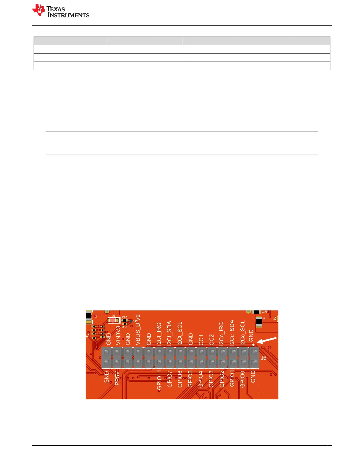
J6 header contains numerous pinout from TPS25751 for testing, evaluation, and debugging purposes. The
header pins are clearly labeled on the top layer of the TPS25751EVM for easy access, for details refer to Table
2-1. Pin 1 is indicated by a white circle, see the picture below for reference.
Figure 2-1. J6 Header
www.ti.com Hardware
SLVUCP9A – NOVEMBER 2023 – REVISED MARCH 2024
Submit Document Feedback
TPS25751 Evaluation Module 5
Copyright © 2024 Texas Instruments Incorporated