4.2.2 Setting up with BQ25792/8EVM
To use the TPS25751EVM and BQ25792EVM, the following items are needed:
1. TPS25751EVM
2. Test hook clips jumper wires
3. TPS25751EVM User Guide and Application Customization Tool
4. BQ25792EVM or BQ25798EVM
5. BQ25792EVM user's guide and data sheet or BQ25798EVM user's guide and data sheet
6. BQStudio with EV2400 [optional]
7. DC Power Supply or Battery Simulator
4.2.2.1 Hardware Setup with BQ25792/8EVM
To setup the hardware, follow the instructions below:
1. Set the J1 jumper of TPS25751EVM to select VBAT for power. Refer to Section 4.2 for details.
2. Use the test hook clips/jumper wires to connect the two EVMs as shown below. See Table 4-1 for details.
3. Refer to BQ25792EVM user's guide or BQ25798EVM user's guide for setting the proper jumper for battery
charging application. Incorrect jumper settings or insufficient input power can result in a faulty evaluation.
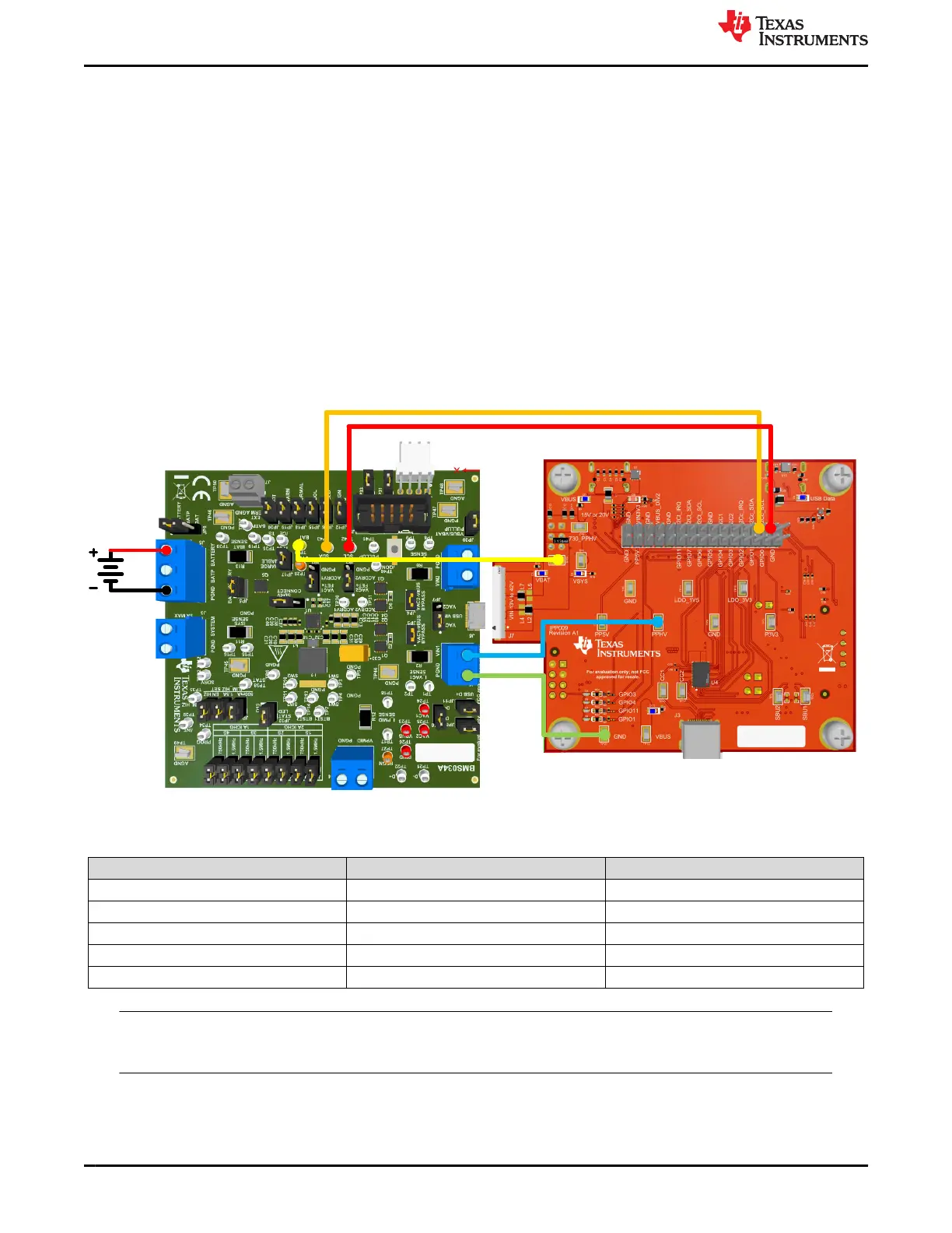
Figure 4-4. TPS25751EVM and BQ25792/8EVM Hardware Setup
Table 4-1. TPS25751EVM and BQ25792/8EVM Connections
Color Designator TPS25751EVM Location BQ25792/8EVM Locator
Red I2Cc_SCL TP42 - SCL
Orange I2Cc_SDA TP43 - SDA
Yellow TP4 - VBAT TP29 - BAT
Blue TP14 - PPHV J1 - VIN1
Green GND PGND
Note
VBAT, PPHV, and GND pins on TPS25751EVM draws significant current, so make sure the cables
used to connect the EVMs are able to support high current (max 5A).
Application Specific Use Case www.ti.com
26 TPS25751 Evaluation Module SLVUCP9A – NOVEMBER 2023 – REVISED MARCH 2024
Submit Document Feedback
Copyright © 2024 Texas Instruments Incorporated