2.5 LED Information
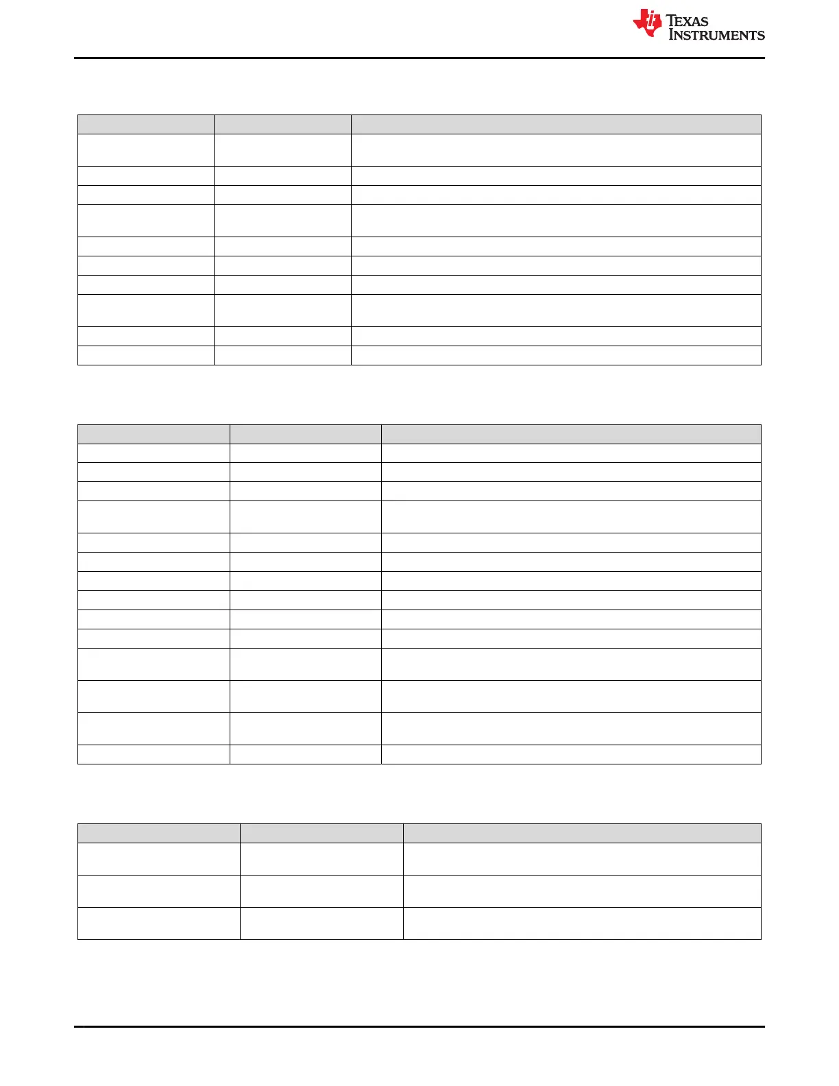
Table 2-3. LEDs
Designator Net Label Description
D1 730_VBUS Blue LED that shows when USB Type-C is connected to Sink Only Type-C Port
(J2).
D2 USB_Data Blue LED that shows when USB Type-C is connected to Data Type-C Port (J4).
D3 VBAT Blue LED that shows when BQ battery is connected to VBAT.
D4 VSYS Blue LED that shows when VBAT or 730_PPHV is supplying system power
(VSYS).
D5 GPIO3 White LED that shows GPIO3 is high.
D6 GPIO2 White LED that shows GPIO2 is high.
D7 GPIO11 White LED that shows GPIO11 is high.
D8 730_CAP_MIS Red LED that shows capability mismatch when an attached source is not providing
enough power to the Sink Only Type-C Port (J2).
D9 GPIO1 White LED that shows GPIO1 is high.
D11 751_VBUS Blue LED that shows when VBUS has a voltage of 5V through 20V
2.6 Test Points
Table 2-4. Test Points
Designator Label Description
TP2 P3V3 3.3V system supply to VIN_3V3 of TPS25751.
TP3 SBU2 SBU2 pin of J3 Type-C Port, used for liquid detection.
TP4 VSYS System power of TPS25751EVM, feeds into 5V and 3.3V power rail.
TP5 730_PPHV TPS25730 high-voltage sinking node in the system, can be connected to
VSYS to provided system power through J1.
TP8, TP9, TP20 GND Ground reference for EVM.
TP10 LDO_3V3 3.3V output of supply switched from VIN_3V3 or VBUS LDO.
TP11 LDO_1V5 1.5V output of the CORE LDO.
TP13 VBUS TPS25751 VBUS voltage reference.
TP14 PPHV TPS25751 high-voltage sinking node in the system.
TP15 PP5V TPS25751 5V system supply to VBUS, supply for CCy pins as VCONN.
TP16 CC1 CC1 pin of J3 Type-C Port, used for PD negotiation. This can be VCONN or
CC depending on the polarity flip of the USB Type-C cable.
TP17 CC2 CC2 pin of J3 Type-C Port, used for PD negotiation. This can be VCONN or
CC depending on the polarity flip of the USB Type-C cable.
TP19 VBAT Battery voltage reference, can be connected to VSYS to provide system
power through J1.
TP22 SBU1 SBU1 pin of J3 Type-C Port, used for liquid detection.
2.7 Switches/Push Buttons
Table 2-5. Switches/Push Buttons
Designator Label Description
S1 ADCIN1 Switch used to set the resistor divider for ADCIN1. Refer to the
TPS25751 data sheet (SLVSH93) on how to configure the pin-strapping.
S2 ADCIN2 Switch used to set the resistor divider for ADCIN2. Refer to the
TPS25751 data sheet (SLVSH93) on how to configure the pin-strapping.
S3 T_RST Push-button to pull the RST pin (38) of the TIVA device. When pressed,
the RST pin goes high.
Hardware www.ti.com
8 TPS25751 Evaluation Module SLVUCP9A – NOVEMBER 2023 – REVISED MARCH 2024
Submit Document Feedback
Copyright © 2024 Texas Instruments Incorporated