4.2.1.1 Hardware Setup with BQ25756(E)EVM
To setup the hardware, follow the instructions below:
1. Set the J1 jumper of TPS25751EVM to select VBAT for power, refer to Section 4.2 for details.
2. Connect the J7 mating connectors of the TPS25751EVM and the BQ25756(E)EVM together.
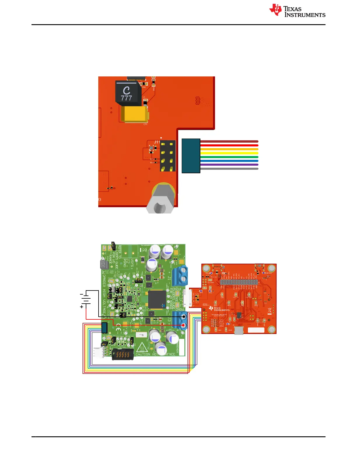
3. On the bottom side of the TPS25751EVM, attach the ribbon cable to J11 header as shown below.
Cable
Latch the cable head
onto J11 jumper
Figure 4-2. Ribbon Cable Connection to J11 header
4. Connect the other end of the ribbon cable to J8 header of the BQ25756(E)EVM. The complete setup is
shown below.
Figure 4-3. TPS25751EVM and BQ25756(E)EVM Hardware Setup
5. Refer to BQ25756EVM user's guide or BQ25756EEVM user's guide for setting the proper jumper for battery
charging application. Incorrect jumper settings or insufficient input power can result in a faulty evaluation.
Application Specific Use Case www.ti.com
24 TPS25751 Evaluation Module SLVUCP9A – NOVEMBER 2023 – REVISED MARCH 2024
Submit Document Feedback
Copyright © 2024 Texas Instruments Incorporated