4.2.1.2 Software Setup with BQ25756(E)EVM
To setup the software configuration, follow the instructions below.
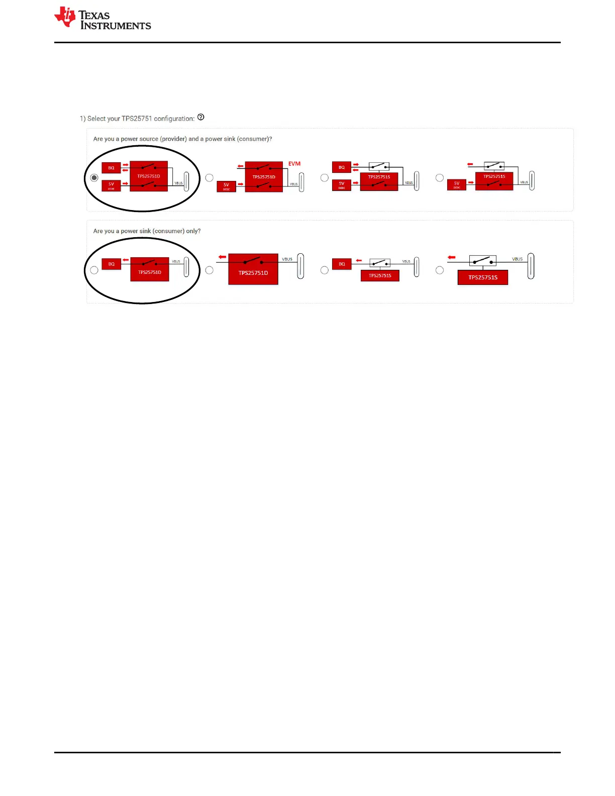
1. Open the Application Customization Tool and select one of the following TPS25751D + BQ configuration
below.
2. Fill out the questionnaire from Q2 to Q10, refer to Section 3.3.3 for more details on each question
configuration. All the questions must be filled out to flash/export.
3. Questions 11 through 18 are for Battery Charger (BQ) Configurations.
4. For Question 11, select BQ25756(E).
5. For Question 12, select the INDPM configuration for the BQ25756(E).
a. For example, if the user selects "5% - INDPM is set to 5% above the negotiated PD Contract Current"
and TPS25751 negotiates a PD contract at 3A, then the INDPM is set to 3.15A.
b. This questionnaire configures register 0x06 - IAC_DPM of BQ25756(E).
6. For Question 13, select the VINDPM configuration for the BQ25756(E).
a. For example, if the user selects "5% - VINDPM is set to 5% below the negotiated PD Contract Voltage"
and TPS25751 negotiates a PD contract at 5V, the VINDPM is set to 4.75V.
b. This questionnaire configures register 0x08 - VAC_DPM of BQ25756(E).
7. For question 14, enter the FB Voltage Regulation Limit in units of Voltage (1.504V through 1.566V, 2mV/bit).
a. This questionnaire configures register 0x00 - VFB_REG of BQ25756(E).
8. For question 15, enter the Charge Current Limit in units of Ampere (0.4A through 20A, 50mA/bit)
a. This questionnaire configures register 0x02 - ICHG_REG of BQ25756(E).
9. For question 16, enter the Charge Termination Current Limit in units of Ampere (0.25A through 10A, 50mA/
bit).
a. This questionnaire configures register 0x12 - ITERM of BQ25756(E).
10. For question 17, enter the Precharge Current Limit in units of Ampere (0.25A through 10A, 50mA/bit).
a. This questionnaire configures register 0x10 - IPRECHG of BQ25756(E).
11. For question 18, enter the Dead Battery Clear Threshold in units of Voltage (2.88V through 19.2V, 64mV/bit).
a. This questionnaire configures register 0x27 - Global System Configuration of TPS25751 and set "Enable
Dead Battery Clear [111]" to '1'.
b. Upon boot-up from dead battery mode (TPS25751 receives power from VBUS first instead of VIN_3V3),
TPS25751 reads register 0x33 - VBAT_ADC of BQ25756.
c. If VBAT voltage is greater or higher than set threshold in Q18, then TPS25751 automatically clear the
dead battery flag, otherwise the dead battery flag remains. Refer to the TPS25751 Technical Reference
Manual for details.
12. Refer to Section 3.3.6 for flashing the configuration or exporting the binary.
www.ti.com Application Specific Use Case
SLVUCP9A – NOVEMBER 2023 – REVISED MARCH 2024
Submit Document Feedback
TPS25751 Evaluation Module 25
Copyright © 2024 Texas Instruments Incorporated