C2000™ Systems Applications Collateral
v2.0
3
Quick Start GUI
The kit comes with a GUI which provides a convenient way to evaluate the functionality of the kit and the
F28035 device without needing to learn and configure the underlying project software or install CCStudio. The
interactive interface using knobs, sliders, buttons, textboxes and graphs enables easy demo of microstepping of
bi-polar stepper motors as well as voltage and current control of brushed DC motors.
Hardware Setup
Note: Do not apply power to board before you have verified these settings!
The kit ships with the control card inserted and the jumper and switch settings pre-selected for connecting with
the GUI. However the user must ensure that these settings are valid on the board.
1) Make sure nothing is connected to the board, and no power is being supplied to the board.
2) Insert the Control card into the J1 controlCARD connector if not already populated.
4) Make sure the following jumpers & connector settings are valid on the DRV8412 base board i.e.
a. JP1 is in the VR1 position
b. JP3 is in the ROCADJ position
c. M1 is in the H position, M2 is in the L position and M3 is in the L position for dual axis Brushed
DC or Stepper motor. In order to run a single Brushed DC motor in parallel H-bridge mode the
user must change the mode jumpers from their default setting. For this mode M1 is in the L
position, M2 is in the H position and M3 is in the L position.
d. Switches S1 and S2 are in the middle position
5) Make sure that the following switches are set as described below on the F28035 controlCARD to enable
boot from flash and connection to the SCI
a. SW3: OFF (UP) position
b. SW2: Position 1 = ON (UP), Position 2 = ON (UP)
6) Connect a USB cable from J1 on the controlCARD to the host computer. LD4 on the controlCARD will
light up indicating that the USB is powered. Windows will then search for a driver for the device. If the
computer has CCSv4 or prior versions of it installed which supported XDS100 emulator, Windows
should be able to find the driver successfully. If not you will be prompted to install the driver. Installing
driver for USB to serial: Do not let Microsoft search for the driver, instead browse to the following
location on the USB stick drive shipped with the kit <Drive Name:\XDS100 Drivers v1.0>, windows
should now be able to find the driver and will install it. If Windows still does not find the driver, you may
have to repeat the process and point to the location pointed out previously. You may have to reboot the
computer for the drivers to come into effect. Once installed you can check if the installation was
completed properly by browsing to ControlPanel-> System->Hardware->Device Manager and looking
for USB Serial Port under Ports(COM&LPT). Note this port number down.
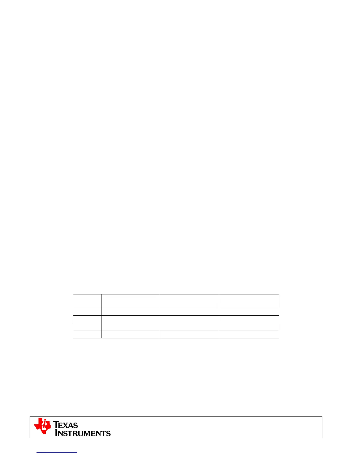
7) Connect the motor(s) you want to spin to the OUTA, OUTB, OUTC and OUTD terminals on the board.
The table below shows the connections for the motors included with the kit.
Terminal Dual Brushed DC Stepper
Single Brushed DC
Parallel Mode
OUTA Motor 1 + Black,Orange/White
Motor +
OUTB Motor 1 - Orange, Black/White
Motor +
OUTC Motor 2 + Red, Yellow/White
Motor -
OUTD Motor 2 - Yellow, Red/White
Motor -
8) Connect the included DC power supply to the PVDD and GND banana jacks.
9) Once the power is connected the board will power up and you will see that the LED1, LED2 and LED3
on the DRV8412EVM base board are green (indicating power), LD1 on the controlCARD is green (also
indicating power) and LD3 (Red) on the controlCARD is blinking slowly indicating that code is running.
Software Setup
The QSG GUI (DRV8412GUIvX.exe) can be located on the drive that is shipped with the kit or once
controlSUITE is installed at the following location:
controlSUITE\developement_kits\DRV8412-EVM\~GUI\DRV8412GUIvX.exe