C2000™ Systems Applications Collateral
v2.0
5
Fig4: GUI Startup
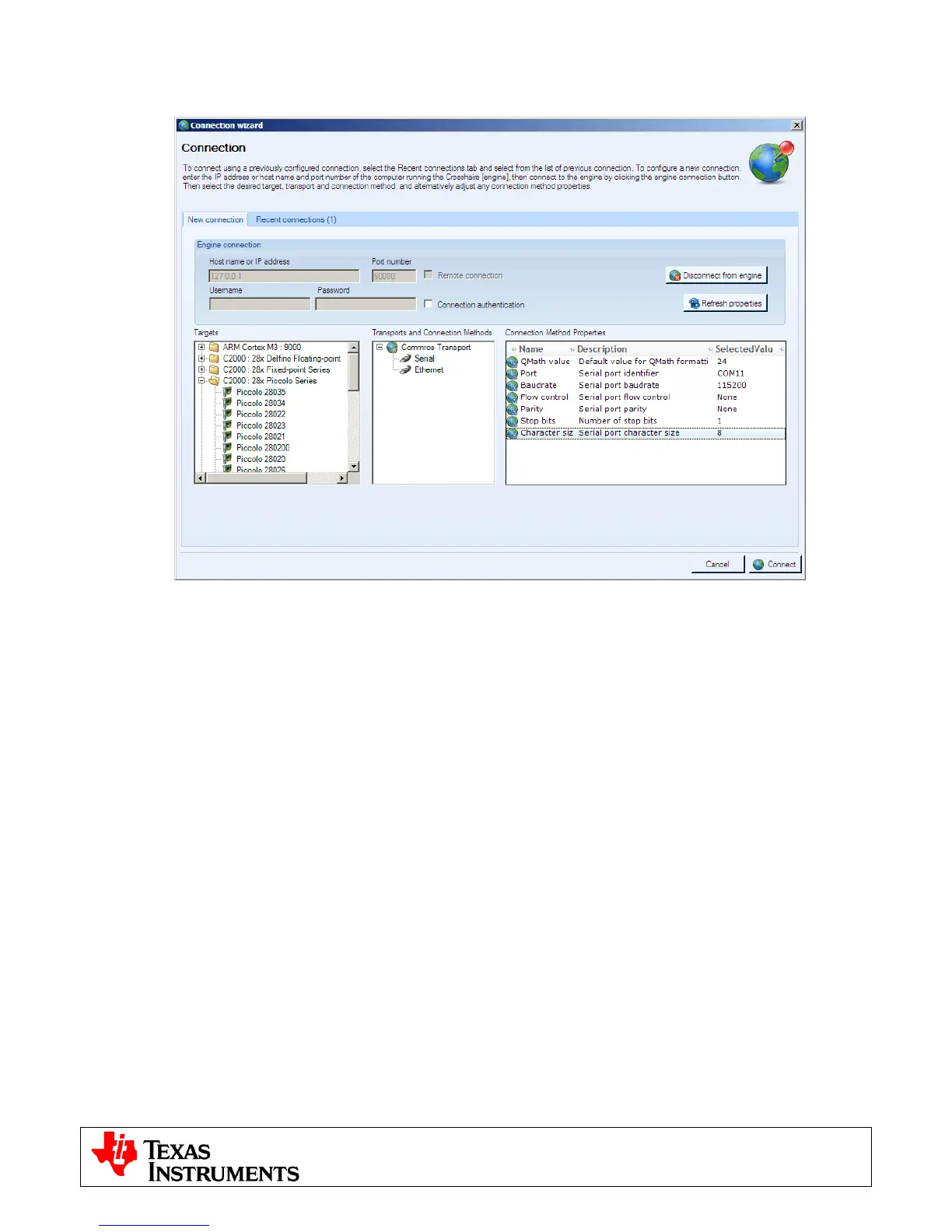
Fig5: GUI Setup Connections
4) If an incorrect image is flashed on the controlCARD the connection will fail. In this case it is
recommended to reflash the controlCARD with the correct image.
5) After the connection is established to the controller the type of motor can be selected by choosing the
corresponding tab in the GUI. If the selection needs to be changed the board should be power
cycled in order to safely connect a different motor.
6) At the bottom of the screen are three sets of controls common to either motor type:
• Enable Motor and Brake on Disable Check boxes: The Enable Motor check box is used to start
or stop the motor(s) from running. The Brake on Disable check box selects the action when the
motor is stopped. If unchecked all H-bridge switches are opened on disable and the motor is free
spinning. If checked the low-side switches are held closed effectively shorting the motor
connections and causing an abrupt stop.
• Fault Status: The on-screen LED will turn red whenever there is a fault signaled by the DRV8412.
To reset this fault ensure Enable Motor check box is unchecked and push the Reset Fault button.
• DC Bus Voltage: The measured DC bus voltage is displayed both digitally and graphically. The on-
screen LED can take three states depending on whether the DC bus is in or out of range. The
range can be adjusted individually for each motor type on the settings tabs.
o Yellow: DC bus is below the minimum value
o Green: DC bus is within limits
o Red: DC bus is above the maximum value