LM2734
V
IN
BOOST
SW
GND
L
D1
D2
D3
R3
C4
V
BOOST
C
BOOST
V
Z
V
IN
C
IN
V
OUT
C
OUT
LM2734
V
IN
BOOST
SW
GND
C
BOOST
L
D1
D2
D3
C
IN
V
IN
C
OUT
V
OUT
V
BOOST
LM2734
www.ti.com
SNVS288I –SEPTEMBER 2004–REVISED APRIIL 2013
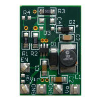
Figure 25. Zener Reduces Boost Voltage from V
IN
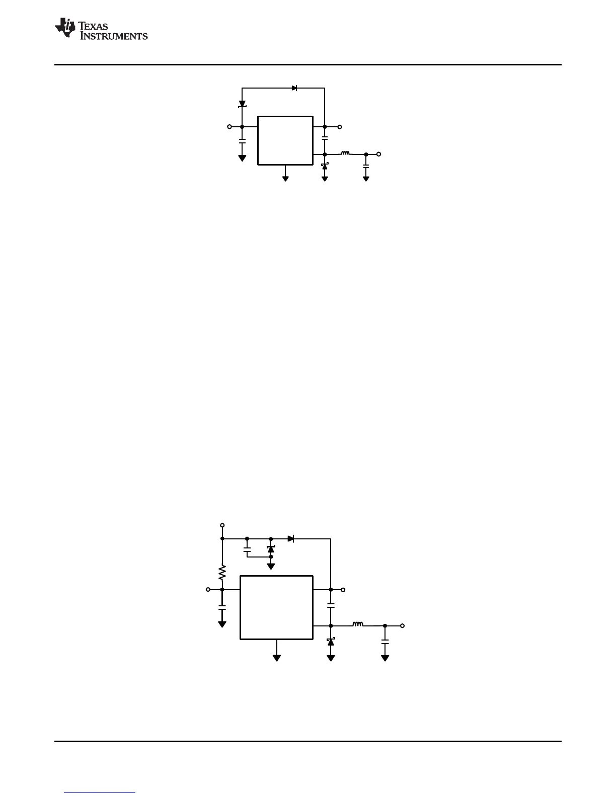
An alternative method is to place the zener diode D3 in a shunt configuration as shown in Figure 26. A small
350mW to 500mW 5.1V zener in a SOT or SOD package can be used for this purpose. A small ceramic
capacitor such as a 6.3V, 0.1µF capacitor (C4) should be placed in parallel with the zener diode. When the
internal NMOS switch turns on, a pulse of current is drawn to charge the internal NMOS gate capacitance. The
0.1 µF parallel shunt capacitor ensures that the V
BOOST
voltage is maintained during this time.
Resistor R3 should be chosen to provide enough RMS current to the zener diode (D3) and to the BOOST pin. A
recommended choice for the zener current (I
ZENER
) is 1 mA. The current I
BOOST
into the BOOST pin supplies the
gate current of the NMOS control switch and varies typically according to the following formula for the X version:
I
BOOST
= 0.56 x (D + 0.54) x (V
ZENER
– V
D2
) mA (6)
I
BOOST
can be calculated for the Y version using the following:
I
BOOST
= 0.22 x (D + 0.54) x (V
ZENER
- V
D2
) µA (7)
where D is the duty cycle, V
ZENER
and V
D2
are in volts, and I
BOOST
is in milliamps. V
ZENER
is the voltage applied to
the anode of the boost diode (D2), and V
D2
is the average forward voltage across D2. Note that this formula for
I
BOOST
gives typical current. For the worst case I
BOOST
, increase the current by 40%. In that case, the worst case
boost current will be
I
BOOST-MAX
= 1.4 x I
BOOST
(8)
R3 will then be given by
R3 = (V
IN
- V
ZENER
) / (1.4 x I
BOOST
+ I
ZENER
) (9)
For example, using the X-version let V
IN
= 10V, V
ZENER
= 5V, V
D2
= 0.7V, I
ZENER
= 1mA, and duty cycle D = 50%.
Then
I
BOOST
= 0.56 x (0.5 + 0.54) x (5 - 0.7) mA = 2.5mA (10)
R3 = (10V - 5V) / (1.4 x 2.5mA + 1mA) = 1.11kΩ (11)
Figure 26. Boost Voltage Supplied from the Shunt Zener on V
IN
Copyright © 2004–2013, Texas Instruments Incorporated Submit Documentation Feedback 11
Product Folder Links: LM2734