15
TPA3116D2
,
TPA3118D2
,
TPA3130D2
www.ti.com
SLOS708G –APRIL 2012–REVISED DECEMBER 2017
Product Folder Links: TPA3116D2 TPA3118D2 TPA3130D2
Submit Documentation FeedbackCopyright © 2012–2017, Texas Instruments Incorporated
Figure 28. Input Impedance
The input capacitors used should be a type with low leakage, like quality electrolytic, tantalum or ceramic. If a
polarized type is used the positive connection should face the input pins which are biased to 3 Vdc.
7.3.3 Startup and Shutdown Operation
The TPA31xxD2 family employs a shutdown mode of operation designed to reduce supply current (Icc) to the
absolute minimum level during periods of nonuse for power conservation. The SDZ input terminal should be held
high (see specification table for trip point) during normal operation when the amplifier is in use. Pulling SDZ low
will put the outputs to mute and the amplifier to enter a low-current state. It is not recommended to leave SDZ
unconnected, because amplifier operation would be unpredictable.
For the best power-off pop performance, place the amplifier in the shutdown mode prior to removing the power
supply. The gain setting is selected at the end of the start-up cycle. At the end of the start-up cycle, the gain is
selected and cannot be changed until the next power-up.
7.3.4 PLIMIT Operation
The TPA31xxD2 family has a built-in voltage limiter that can be used to limit the output voltage level below the
supply rail, the amplifier simply operates as if it was powered by a lower supply voltage, and thereby limits the
output power. Add a resistor divider from GVDD to ground to set the voltage at the PLIMIT pin. An external
reference may also be used if tighter tolerance is required. Add a 1 µ F capacitor from pin PLIMIT to ground to
ensure stability. It is recommended to connect PLIMIT to GVDD when using 1SPW-modulation mode.
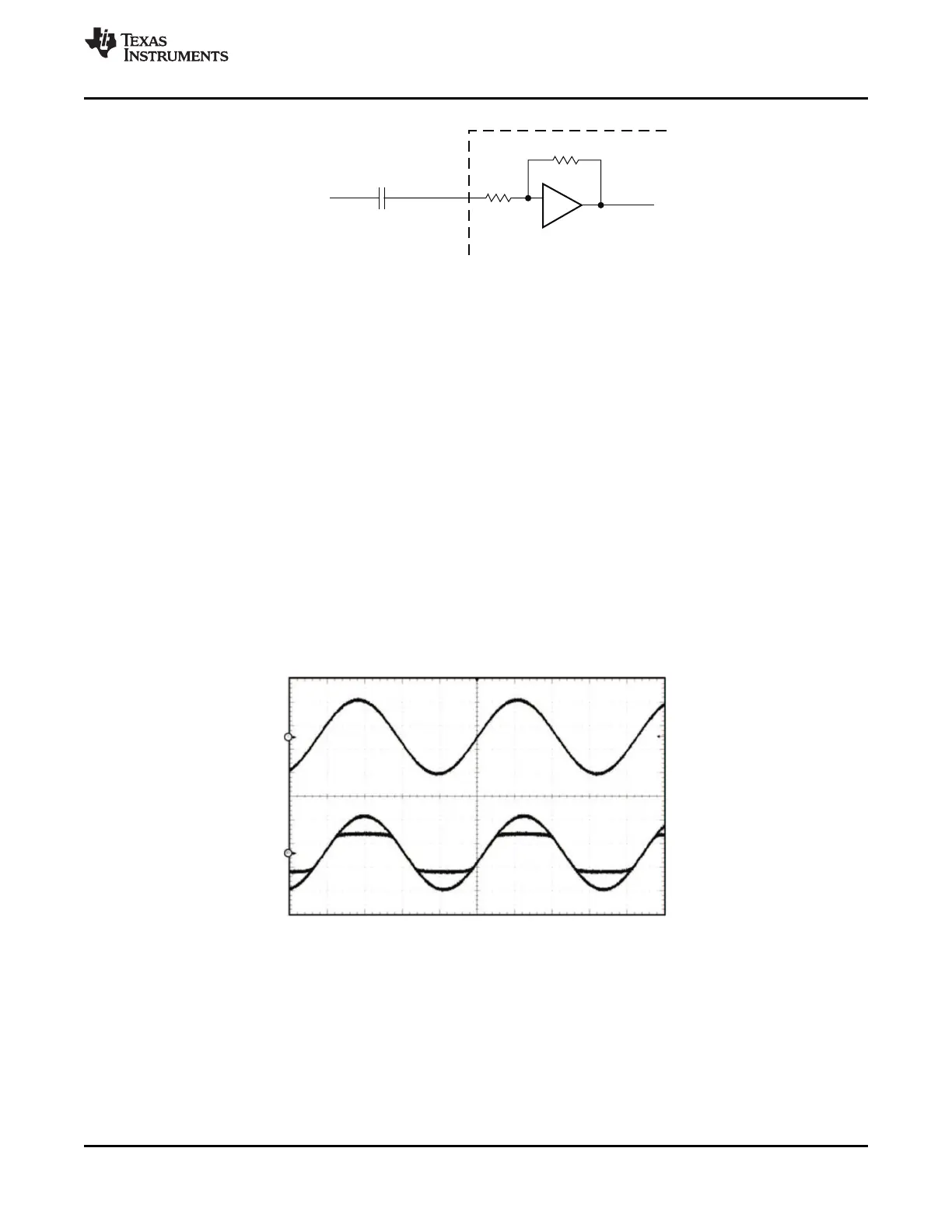
Figure 29. Power Limit Example
The PLIMIT circuit sets a limit on the output peak-to-peak voltage. The limiting is done by limiting the duty cycle
to a fixed maximum value. This limit can be thought of as a "virtual" voltage rail which is lower than the supply
connected to PVCC. This "virtual" rail is approximately 4 times the voltage at the PLIMIT pin. This output voltage
can be used to calculate the maximum output power for a given maximum input voltage and speaker impedance.
 Loading...