4
TPA3116D2
,
TPA3118D2
,
TPA3130D2
SLOS708G –APRIL 2012–REVISED DECEMBER 2017
www.ti.com
Product Folder Links: TPA3116D2 TPA3118D2 TPA3130D2
Submit Documentation Feedback Copyright © 2012–2017, Texas Instruments Incorporated
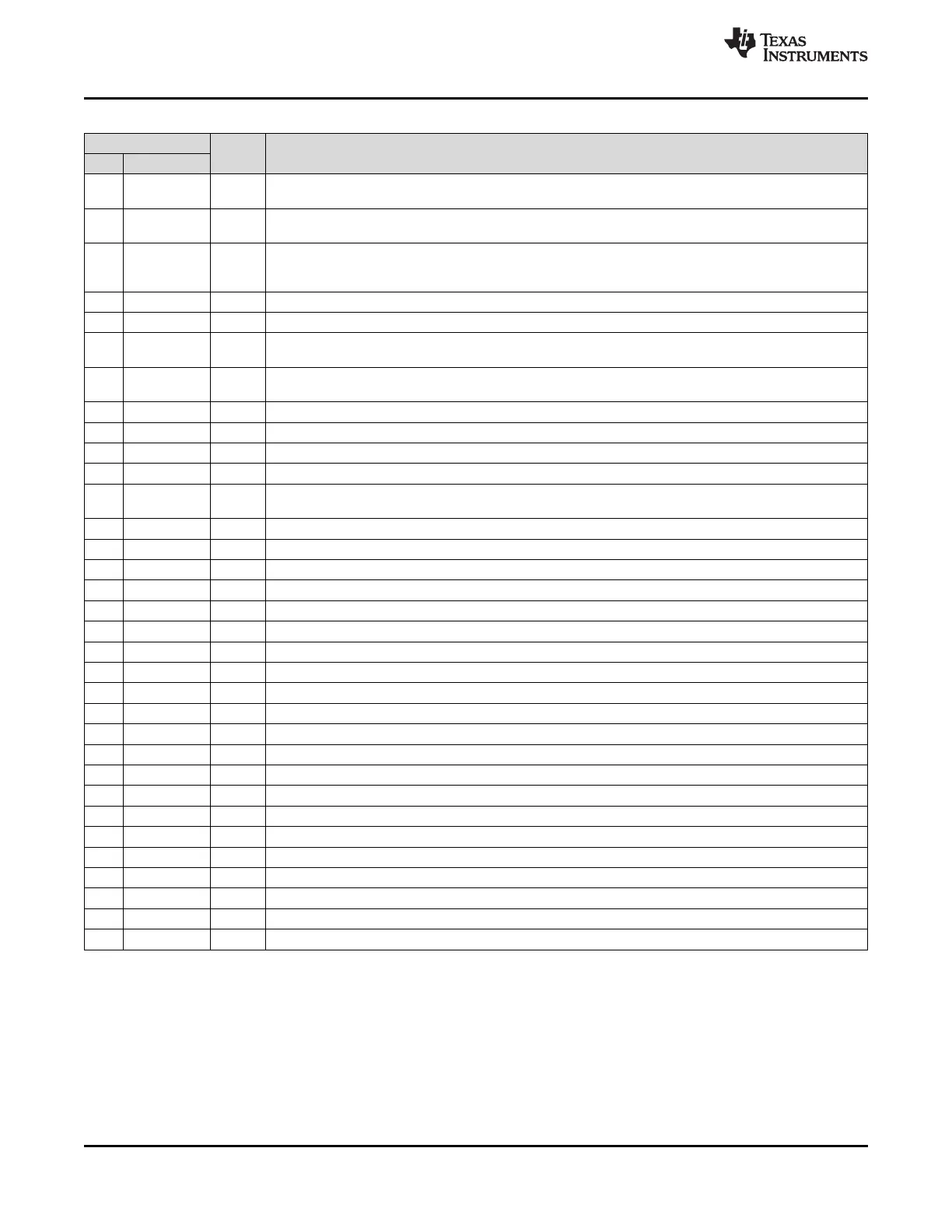
(1) TYPE: DO = Digital Output, I = Analog Input, G = General Ground, PO = Power Output, BST = Boot Strap.
Pin Functions
PIN
TYPE
(1)
DESCRIPTION
NO. NAME
1 MODSEL I Mode selection logic input (LOW = BD mode, HIGH = 1 SPW mode). TTL logic levels with compliance to
AVCC.
2 SDZ I Shutdown logic input for audio amp (LOW = outputs Hi-Z, HIGH = outputs enabled). TTL logic levels with
compliance to AVCC.
3 FAULTZ DO General fault reporting including Over-temp, DC Detect. Open drain.
FAULTZ = High, normal operation
FAULTZ = Low, fault condition
4 RINP I Positive audio input for right channel. Biased at 3 V.
5 RINN I Negative audio input for right channel. Biased at 3 V.
6 PLIMIT I Power limit level adjust. Connect a resistor divider from GVDD to GND to set power limit. Connect directly
to GVDD for no power limit.
7 GVDD PO Internally generated gate voltage supply. Not to be used as a supply or connected to any component other
than a 1 µF X7R ceramic decoupling capacitor and the PLIMIT and GAIN/SLV resistor dividers.
8 GAIN/SLV I Selects Gain and selects between Master and Slave mode depending on pin voltage divider.
9 GND G Ground
10 LINP I Positive audio input for left channel. Biased at 3 V. Connect to GND for PBTL mode.
11 LINN I Negative audio input for left channel. Biased at 3 V. Connect to GND for PBTL mode.
12 MUTE I Mute signal for fast disable/enable of outputs (HIGH = outputs Hi-Z, LOW = outputs enabled). TTL logic
levels with compliance to AVCC.
13 AM2 I AM Avoidance Frequency Selection
14 AM1 I AM Avoidance Frequency Selection
15 AM0 I AM Avoidance Frequency Selection
16 SYNC DIO Clock input/output for synchronizing multiple class-D devices. Direction determined by GAIN/SLV terminal.
17 AVCC P Analog Supply
18 PVCC P Power supply
19 PVCC P Power supply
20 BSNL BST Boot strap for negative left channel output, connect to 220 nF X5R, or better ceramic cap to OUTNL
21 OUTNL PO Negative left channel output
22 GND G Ground
23 OUTPL PO Positive left channel output
24 BSPL BST Boot strap for positive left channel output, connect to 220 nF X5R, or better ceramic cap to OUTPL
25 GND G Ground
26 BSNR BST Boot strap for negative right channel output, connect to 220 nF X5R, or better ceramic cap to OUTNR
27 OUTNR PO Negative right channel output
28 GND G Ground
29 OUTPR PO Positive right channel output
30 BSPR BST Boot strap for positive right channel output, connect to 220 nF X5R or better ceramic cap to OUTPR
31 PVCC P Power supply
32 PVCC P Power supply
33 PowerPAD G Connect to GND for best system performance. If not connected to GND, leave floating.
 Loading...