27
TPA3116D2
,
TPA3118D2
,
TPA3130D2
www.ti.com
SLOS708G –APRIL 2012–REVISED DECEMBER 2017
Product Folder Links: TPA3116D2 TPA3118D2 TPA3130D2
Submit Documentation FeedbackCopyright © 2012–2017, Texas Instruments Incorporated
Typical Application (continued)
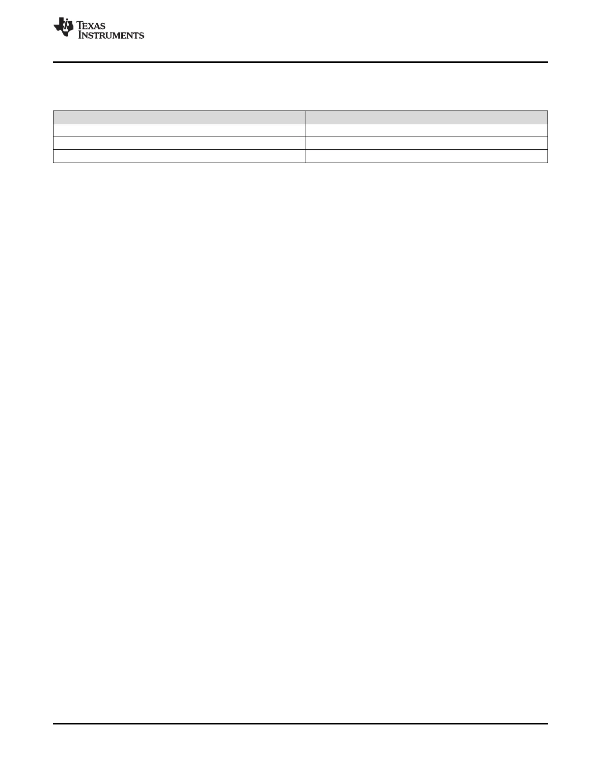
8.2.1 Design Requirements
DESIGN PARAMETERS EXAMPLE VALUE
Input voltage range PVCC 4.5 V to 26 V
PWM output frequencies 400 kHz, 500 kHz, 600 kHz, 1 MHz or 1.2 MHz
Maximum output power 50 W
8.2.2 Detailed Design Procedure
The TPA31xxD2 family is a very flexible and easy to use Class D amplifier; therefore the design process is
straightforward. Before beginning the design, gather the following information regarding the audio system.
• PVCC rail planned for the design
• Speaker or load impedance
• Maximum output power requirement
• Desired PWM frequency
8.2.2.1 Select the PWM Frequency
Set the PWM frequency by using AM0, AM1 and AM2 pins.
8.2.2.2 Select the Amplifier Gain and Master/Slave Mode
In order to select the amplifier gain setting, the designer must determine the maximum power target and the
speaker impedance. Once these parameters have been determined, calculate the required output voltage swing
which delivers the maximum output power.
Choose the lowest analog gain setting that corresponds to produce an output voltage swing greater than the
required output swing for maximum power. The analog gain and master/slave mode can be set by selecting the
voltage divider resistors (R1 and R2) on the Gain/SLV pin.
8.2.2.3 Select Input Capacitance
Select the bulk capacitors at the PVCC inputs for proper voltage margin and adequate capacitance to support the
power requirements. In practice, with a well-designed power supply, two 100-μF, 50-V capacitors should be
sufficient. One capacitor should be placed near the PVCC inputs at each side of the device. PVCC capacitors
should be a low ESR type because they are being used in a high-speed switching application.
8.2.2.4 Select Decoupling Capacitors
Good quality decoupling capacitors need to be added at each of the PVCC inputs to provide good reliability,
good audio performance, and to meet regulatory requirements. X5R or better ratings should be used in this
application. Consider temperature, ripple current, and voltage overshoots when selecting decoupling capacitors.
Also, these decoupling capacitors should be located near the PVCC and GND connections to the device in order
to minimize series inductances.
8.2.2.5 Select Bootstrap Capacitors
Each of the outputs require bootstrap capacitors to provide gate drive for the high-side output FETs. For this
design, use 0.22-μF, 25-V capacitors of X5R quality or better.
 Loading...