Vs
RL
Vbus
Q1
D1
Cb
Signal
Conditioning
Rs1
EMI Filter
& Inrush
Relay
Gate
Driver
L1
Iin
D2
Signal
Conditioning
Signal
Conditioning
Vin
Iq1
DPWM 1B
Vin_L
Vbus_sen
I_shunt
Vin_N
Vbus_ov
Single-phase PFC
Circuit Diagram
Signal
Conditioning
I_CT1
www.ti.com
Digital PFC Description
12 Digital PFC Description
12.1 1PFC Block Diagram
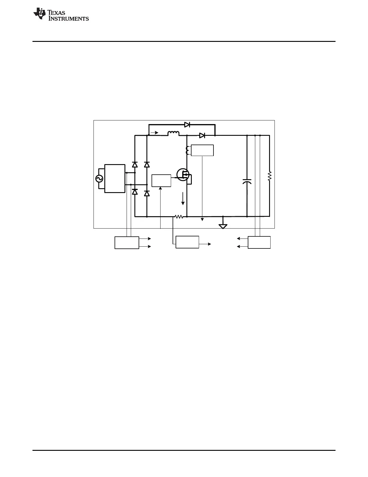
12.1.1 Single-Phase PFC Block Diagram
Single-phase PFC function block diagram is shown in Figure 25. The digital controlled single-phase PFC
has the same power stage as those seen in other analog controlled devices. The main difference is the
line voltage is sensed then rectified inside the UCD3138 digital controller. All signals interact with
UCD3138 and explained in section Section 12.2.
Figure 25. Digitally Controlled Single-Phase PFC System Block Diagram
25
SLUU885B–March 2012–Revised July 2012 Digitally Controlled Single-Phase PFC Pre-Regulator
Submit Documentation Feedback
Copyright © 2012, Texas Instruments Incorporated