Evaluating the Single-Phase PFC with GUI
www.ti.com
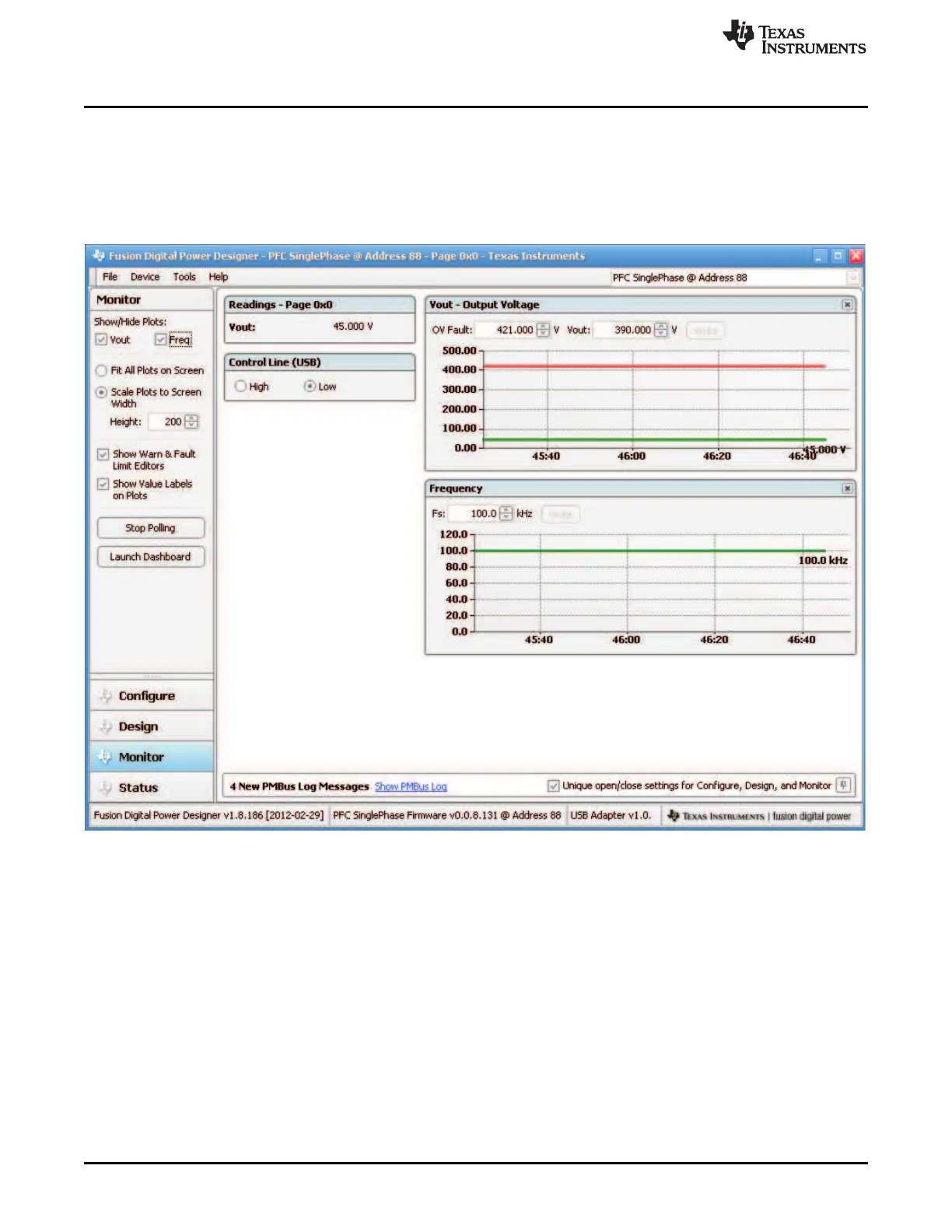
13.3 Overview of the Designer GUI
When the designer GUI is open, it identifies the connected board by the ID in the firmware. Figure 42
shows the opened GUI. The Designer GUI provides various assistance to access the firmware codes
indirectly. For the full set of the functions that the Designer GUI can provide, please refer to the user’s
manual. In this application note, we focus on how to make monitoring, board re-configuring and re-tuning
to show basic aspects on how to use the GUI in a typical power supply design evaluation on a bench test.
Figure 42. Designer GUI Overview
13.3.1 Monitor
On the lower left corner of that shown in Figure 42, there are four tabs, called Configure, Design, Monitor
and Status. Clicking each tab brings a unique page to the front of that page. The clicked tab is highlighted
in blue. Figure 42 shows Monitor tab was clicked. The page shows all variables in monitoring with
UCD3138 single-phase PFC. These variables are communicated through PMBus. Adding more variables
in Monitoring is possible but has to be executed through the firmware code change and re-compile
process.
46
Digitally Controlled Single-Phase PFC Pre-Regulator SLUU885B–March 2012–Revised July 2012
Submit Documentation Feedback
Copyright © 2012, Texas Instruments Incorporated