PI P I
1
1
G (z) K K
1 z
-
= +
-
Monitoring, Re-configuring and Re-tuning with Designer GUI
www.ti.com
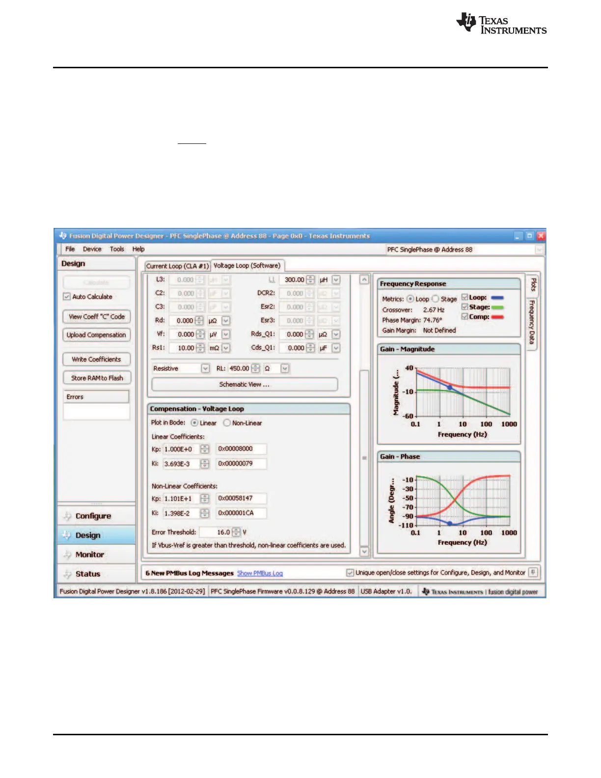
14.4.3 Voltage Loop Evaluation and Re-tuning
Voltage loop can be evaluated and re-tuned in a similar way. Figure 49 shows voltage loop PI control
coefficients and corresponding bode plots.
The voltage loop PI control is implemented with software and has the below form,
(19)
There are two sets of the PI coefficients for voltage loop control. In normal operation, the control is with
Linear Coefficients. In transient when the PFC output bulk voltage exceeds the defined Error Threshold,
for example, 16.0 V, as shown, the PI control coefficients are changed to Non-Linear Coefficients to
achieve better transient response and to eliminate the output large deviation faster. The output error
threshold is usually within 5% of the output set point, or within 20 V on 390-V
DC
output.
Figure 49. Voltage Loop PI Control Re-Tuning
54
Digitally Controlled Single-Phase PFC Pre-Regulator SLUU885B–March 2012–Revised July 2012
Submit Documentation Feedback
Copyright © 2012, Texas Instruments Incorporated