INS154-7 5/17
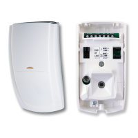
1.4 Wiring The Unit
Connect the unit to the control panel as follows:
A (12V) Permanent
Positive Supply
B (BELL) Negative
Applied Output to Activate Siren
C (TAMP) Negative
Removed on Tamper Input
D (0V) Permanent
Negative Supply
S (STRB) Negative Applied
Output to Activate Strobe
T (Test)* Test input for enabling
remote test via Maintex or Wintex, or any
supporting panel.
Tamper Relay* Negative Removed on
Tamper Input, and reports Tamper when
there is a power loss to the sounder. (
Fault Relay* Reports Faults from
the sounder
N * Premier Elite Sounders only
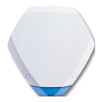
For safety reasons, each Texecom sounder and strobe unit incorporates a unique
patented engineer Hold‑Off mode. This mode prevents the unit from self-activating
during installation and maintenance, thereby allowing only bona fide engineers