Odyssey X Installation Manual
INS627-2 9
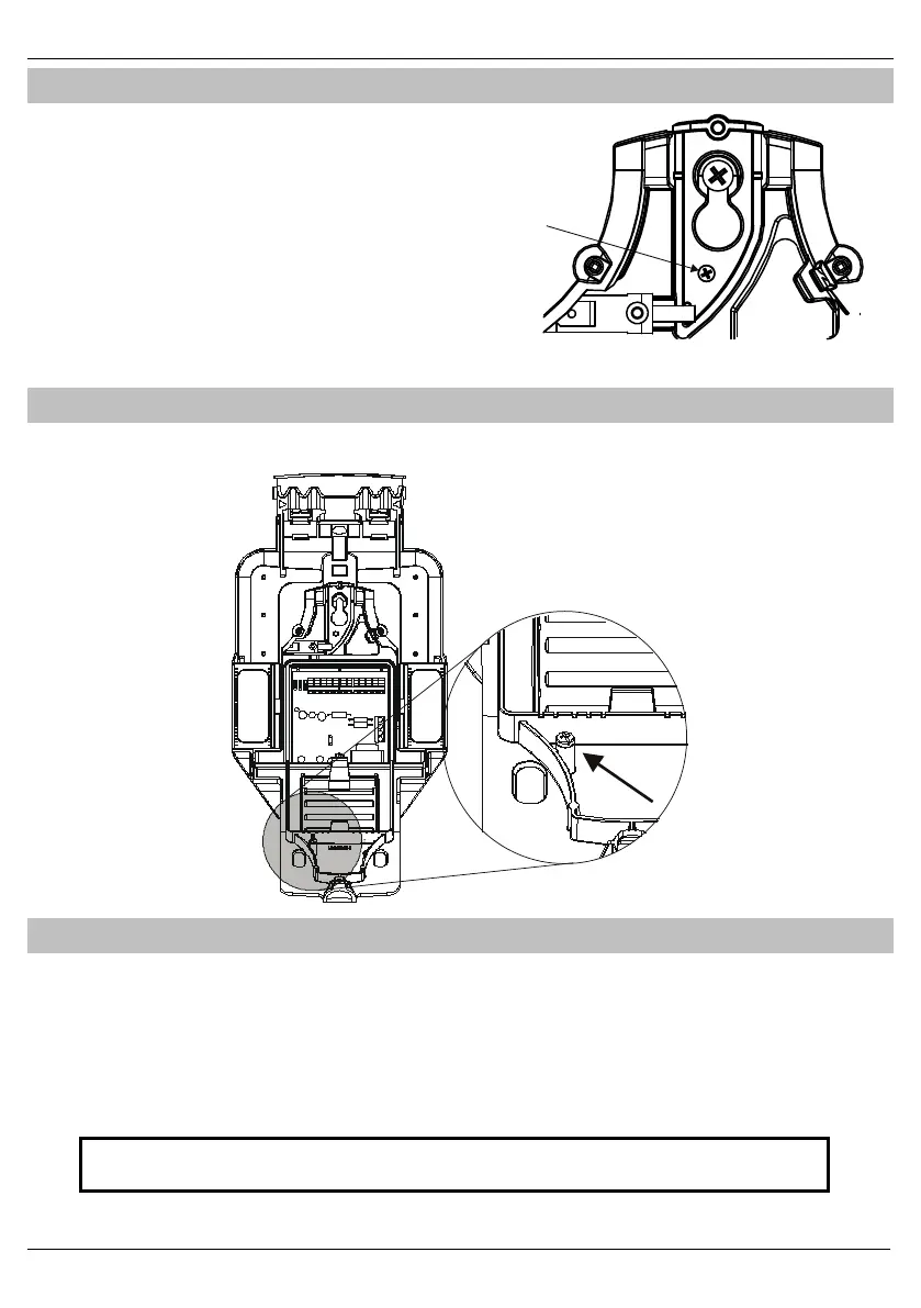
Adjusting removal from mounting tamper
The removal from mounting tamper screw must be used on all surfaces; on
uneven surfaces it will prevent the keyhole screw from damaging the tamper
breakout. .
The screw should be driven in until it makes contact with the wall.
Failure to do this may result in incorrect operation of the tamper
circuit.
Internal Lid Tamper
The Odyssey X is fitted with an internal lid tamper to prevent access to the electronics and wiring of the unit. The screw located on the inside of
the internal hinged lid should be adjusted so that the tamper switch closes correctly when the lid is screwed into place.
Wiring the Unit
Connect the unit to the control panel as follows:
A (12V) Permanent Positive Supply
B (BELL) Negative Applied Output to Activate Siren
C (TAMP) Negative Removed on Tamper Input
D (0V) Permanent Negative Supply
S (STRB) Negative Applied Output to Activate Strobe
T (Test) Test input for enabling remote test via
Maintex or Wintex*
Tamper Relay Negative Removed on Tamper Input*
Fault Relay Reports Faults from the sounder*
* Not applicable to Odyssey X-E & X-BE
Although the unit has been designed to be compatible with a wide range of control panels, for optimum performance, it is
highly recommended that the unit should be used with Texecom's range of control panels.