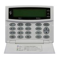
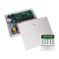
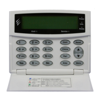
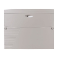
Premier Elite 12-W/24-W/48-W Quick Start Guide
INS531-4 3
Control Panel Features
Premier Elite 12-W/24-W/48-W
• 4 Onboard Zones
• Max 8,16 or 32 wireless device Ricochet enabled receiver onboard
• Expandable to 12-48 zones via keypads and zone expanders
• 1 x 4-wire data network (standard 7/0.2 alarm cable)
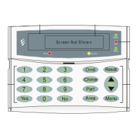
• Up to 4 keypads (2 only on the 12-W) and 0-3 zone expanders
• Up to 2 output modules (0 on 12-W)
• 2 or 4 independent areas each with 3 part arms
• 2 or 4 area arm suites
• 8 (12-W), 25 (24-W), or 50 (48-W), programmable User codes
• 250 (12-W) or 500 (24-W/48-W) Event Log (time & date stamped)
• 1 or 2 programmable panel outputs (2 x 500mA )
• 1.5 Amp power supply
• 32 Event Alarm Log
• 3 or 8 programmable digicom outputs (100mA each)
• 32 character zone text
• Facility for Plug-on Digimodem (Com300/2400/)
• Facility for Plug-on GSM Module
• Facility for Plug-on IP Module (ComIP/Chiron/WebWayOne/Emizon) or any
supported device
• PC-Com/printer port
Power Supply Ratings
Battery
Arrangement
Battery
Charge
Rated Output (Amps)
12h
1 x 7Ah 0.3A 0.433A
The “Rated Power” of the control panel will depend on the size of the standby
battery, standby time and the installation grade:
EN50131-1 Grade 1 Grade 2
Minimum Standby Period 12h 12h
Maximum Recharge Time 72 Hrs 72 Hrs
PD6662 Grade 1 Grade 2
Maximum Recharge Time 72 Hrs 72 Hrs
Connecting AC Mains
The AC Mains supply is connected to a 3 way ‘Euro Type’ fused terminal block,
which is fitted with a 3A - 3.15A slow/medium blow fuse.
All other wiring MUST be carried out before AC mains is
connected to the control panel.
After connecting the AC Mains, fit the mains cover, this can be found in
the spares bag.
Installation
This manual is a quick start guide and details how to learn Ricochet devices to the system, full programming details for all other system features and functions can be
found in INS176-X contained on the enclosed CD.
Installation Sequence
Before attempting to install the alarm system, read this section. Once you have
an overall understanding of the installation sequence, carefully work through
each step.
1: Design the Layout
Make a rough sketch of the premises to get an idea of where the alarm
detection devices, keypads, zone expanders etc. are to be located.
2: Mounting the Panel
The control panel should be mounted in a dry area close to an unswitched AC
power source and the incoming telephone line (if using a communicator).
You must complete all wiring before connecting the battery or
applying AC mains to the control panel.
3: Install the Keypads and Zone Expanders
Mount and connect the keypads, zone expanders and output modules to the
control panel.
If using a hardwired expander in addition to the wireless devices,
numbering should start at address 2.
4: Install the External Sounder
Install the external sounder and connect to the control panel.
5: Other Wiring
Complete all other wiring including speakers, telephone line and output
connections etc.
6: Applying Power to the Control Panel
Once steps 1 to 5 are completed, power can be applied to the control panel.
When applying power for the first time, the factory default settings must be
loaded. Power should always be connected in the following order:
• Connect the red battery lead to the positive terminal of the battery and
then connect the black battery lead to the negative terminal
The panel will only become ‘live’ when the AC Mains is connected
or the ‘Battery Kick-start’ button is pressed.
• Connect the AC mains
For a complete list of factory default settings, see the Premier Quick
Reference supplied with your panel.
8: Learn Ricochet™ Devices
Learn devices to the system and place them in their desired location.
9: Programming the Control Panel
Please refer to INS176 for instructions on programming the control panel.
10: Testing the System
Test the system thoroughly to ensure that all features and functions operate as
required.

 Loading...

