Do you have a question about the Texecom Premier 412 Premier 816 Premier 832 and is the answer not in the manual?
Describes the system components and their interconnections within the alarm panel.
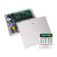
Details the features and specifications of the Premier 412, 816, and 832 control panels.
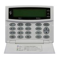
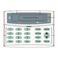
Describes various remote keypad models supported, including their features and connections.
Explains the Premier 8X Remote and 8XE Local Zone Expanders for system expansion.
Details the PC-Com module for RS232 interface for printer and PC communication.
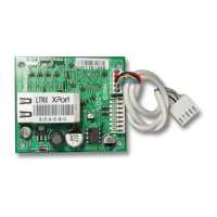
Describes the ComIP module for TCP/IP alarm reporting and system programming.
Details the Speech Module for providing audible alerts and messages.
Explains the Radio Receiver Module for integrating wireless devices.
Outlines the step-by-step process for installing the alarm system.
Covers the physical mounting and wiring of the main control panel unit.
Details installing keypads, connecting zone wiring, and other external devices.
Provides guidance on installing power supplies and managing cable voltage drop.
Covers applying power, initial programming, and performing system tests.
Details AC input, battery, and auxiliary 12V power connections on the PCB.
Describes connections for the data bus, zone inputs, and communication ports.
Details Siren/Spk output, Panel Outputs, and Two-Wire Smoke Detector setups.
Covers the programmable auxiliary input and other specific PCB terminals.
Explains how to wire devices to the control panel's data bus terminals.
Details the maximum recommended cable lengths for data bus connections.
Describes the physical layout, speaker output, and backlighting of various keypads.
Details connecting keypads to the data bus and setting their unique addresses.
Explains programmable zone inputs and programmable outputs on specific keypads.
Covers disabling the keypad lid tamper function.
Describes the physical layout and data bus connection for the zone expander.
Explains how to set the address for the remote zone expander using DIL switches.
Details how zones are allocated when using the remote zone expander module.
Shows the layout and terminal connections for the local zone expander.
Provides step-by-step instructions for fitting the local zone expander to the control panel.
Describes wiring methods for normally closed and normally open detection devices.
Explains single EOL wiring for N/C, N/O, tamper, and fire detection devices.
Details wiring for double EOL, zone doubling, and their implications.
Describes wiring configurations for Triple EOL detectors and double pole circuits.
Details how to connect compatible 2-wire smoke detectors to Panel Output 1.
Explains configuring the Siren/Spk output for siren, bell, or speaker operation.
Details how to supervise the siren/speaker output and resolve faults.
Describes connecting the control panel to the telephone line for communication.
Lists the electrical characteristics (supervised, current, type) for each panel output.
Shows typical wiring configurations for LED indication, 12V buzzer, and relay drivers.
Explains how to configure supervision for outputs 1 and 2 or disable it.
Covers the initial power-up sequence, default settings loading, and basic programming.
Diagnoses and resolves issues related to power supply faults for mains and battery.
Addresses issues with keypads not operating or not accepting access codes.
Troubleshoots issues with zones not being recognized or expanders not operating.
Diagnoses problems with the communicator failing to dial or communicate.
| Brand | Texecom |
|---|---|
| Model | Premier 412 Premier 816 Premier 832 |
| Category | Control Panel |
| Language | English |
