Installation Premier 412/816/832 Installation Manual
18 INS159
Panel Outputs 1 - 8
The control panel has eight programmable outputs, which
can be used to drive auxiliary devices such as relays, LED’s,
smoke detectors etc. The table below shows the electrical
characteristics for each output:
No Supervised Max Current Type
1 Yes 1 Amp Switched –ve
2 Yes 1 Amp Switched –ve
3 No 100mA Switched –ve
4 No 100mA Switched –ve
5 No 100mA Switched –ve
6 No 100mA Switched –ve
7 No 100mA Switched –ve
8 No 100mA Switched –ve
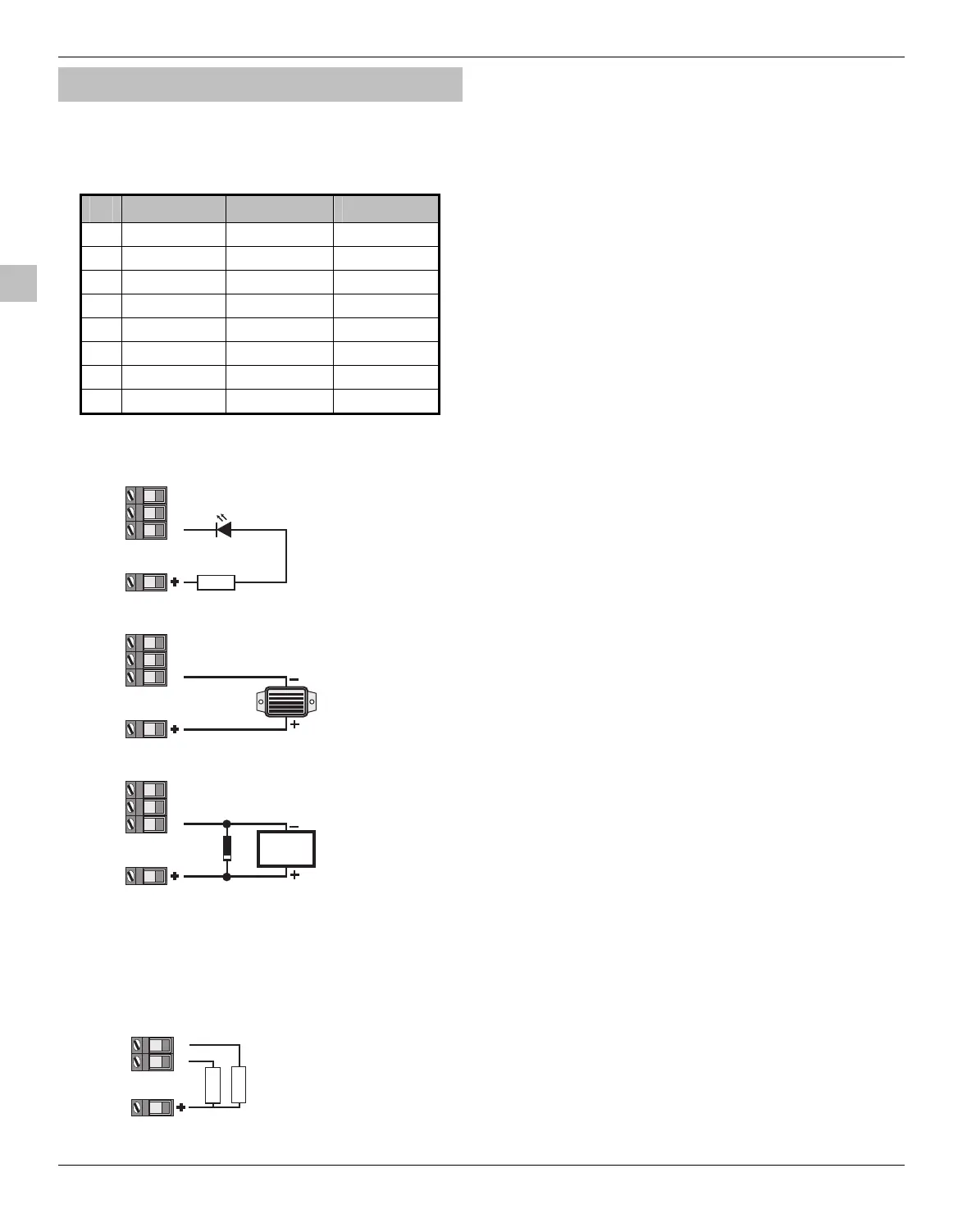
Output Wiring
The figure below shows some typical wiring examples:
LED
1K
Panel Outputs
Aux 12
1
23
LED Indication
12V Buzzer
Panel Outputs
Aux 12
1
23
Relay Driver
Diode
(IN4148)
Relay
Panel Outputs
Aux 12
1
23
Output Supervision
Panel outputs 1 and 2 are supervised, if either output is
unused, either disable the relevant output supervision (see
page 36 for details) or connect a 1KΩ resistor between the
relevant output terminal and Auxiliary 12V+ as shown:
1
1K
If output 1 or 2 is unused,
connect a 1K resistor as shown.
2
1K
Panel Outputs
Aux 12
 Loading...


