Premier 412/816/832 Installation Manual Installation
INS159 9
The table below shows maximum cable runs when one
keypad or expander is installed using standard 7/0.2 alarm
cable with various loads:
Configuration Max. Cable Run
1. Keypad + 2 PIR’s @15mA 250m
2. Expander + 2 PIR’s @15mA 250m
3. Expander + 8 PIR’s @15mA 100m
4. As No. 3 + 16Ω Speaker 30m
Overcoming Voltage Drop
There are several ways to overcome voltage drop:
• Use thicker lower resistance cable. Standard 7/0.2
alarm cable has a resistance of 8Ω per 100m
• Double up on the power connections – this will require
using a 6 or 8-core cable rather than a 4-core cable
• Install a power supply to power the device locally,
remember to common the two negative connections
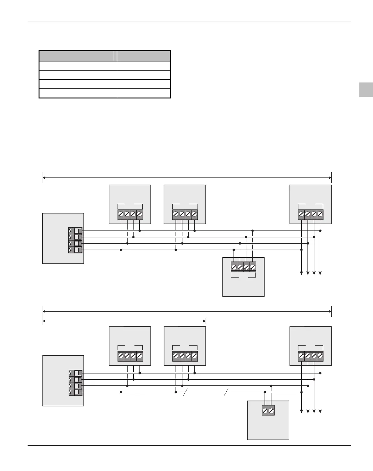
Installing a Power Supply
When a power supply is installed, the 0V connections on the
power supply must be connected through to 0V on the
control panel and the +12V connection between the control
panel and the device must be disconnected (see figure
below).
Control Panel
+
TR
Remote Keypad
-
Data
Data Bus
+
TR
-
+
TR
Remote Keypad
-
Data
+
TR
Remote Keypad
-
Data
Remote Expander
+
TR
-
Data
To additional
devices
250 metres
Control Panel
Data Bus
+
TR
-
+
TR
Remote Keypad
-
Data
+
TR
Remote Keypad
-
Data
+
TR
Remote Keypad
-
Data
12V Power Supply
+
-
To additional
devices
1 Kilometre
Disconnect +12V
from control panel
250 metres
Data Bus Connections (250m without additional power supply).
Data Bus Connections (1Km with additional power supply).
 Loading...


