Installation Premier 412/816/832 Installation Manual
8 INS159
11: Communication Port
The serial communication port is used for connecting to a
printer or PC for local downloading.
12: Load Defaults
Short between the centre and either of the outer pins during
power up to restore the control panel default program
parameters. These pins can also be used to reset the
Engineer code back to its default value, see page 67.
!
Do not leave these pins shorted, otherwise the control
panel event log will be erased.
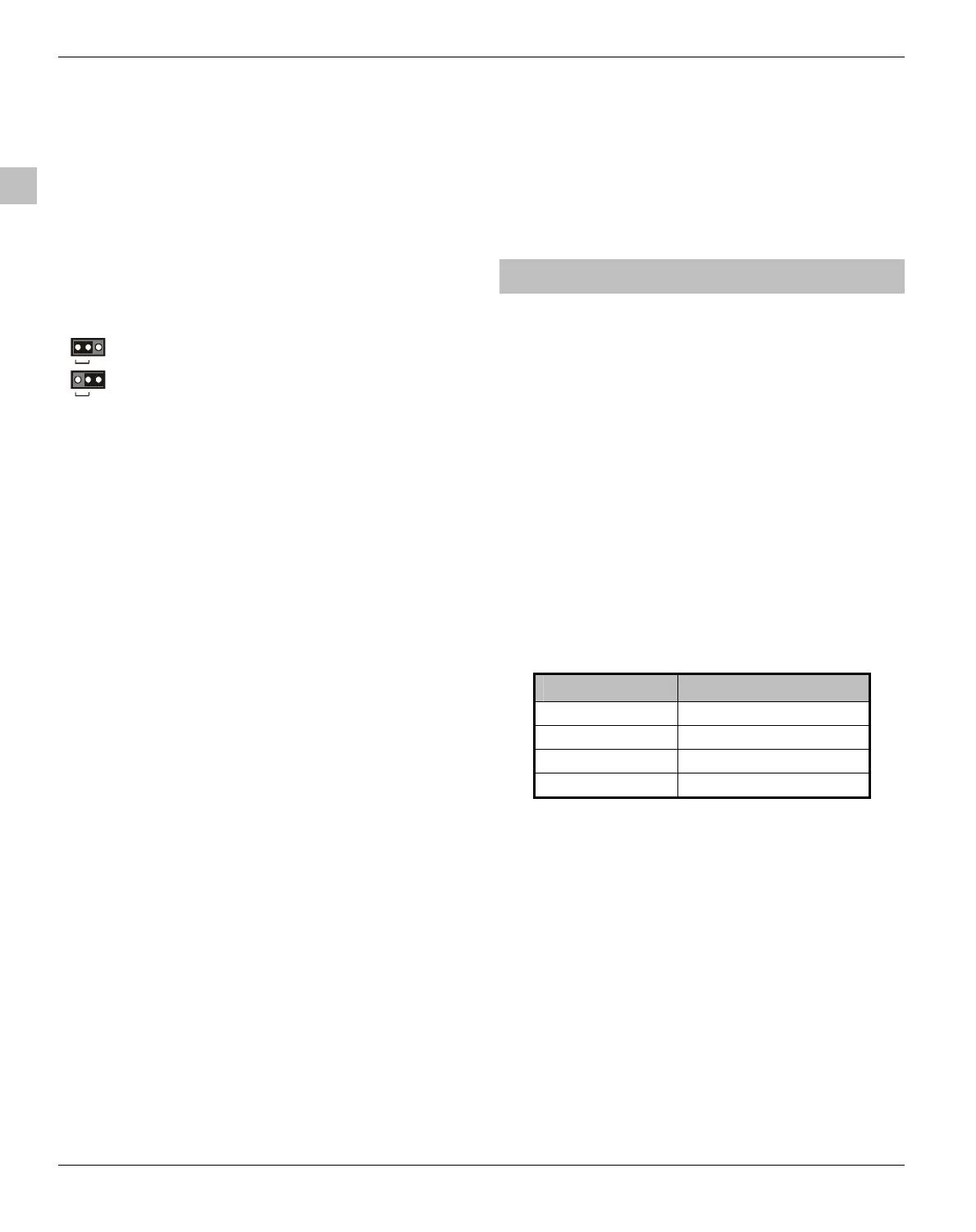
13: Box Tamper Disable
Fit link as shown:
Box Tamper Disabled
Box Tamper Enabled
14: Local Zone Expander
The Premier 8XE Local Zone Expander can be plugged on to
the main PCB. The local expander provides an additional 8
programmable zones (see page 12).
15: Speech Module
A two channel Speech Module can be plugged on to the
main PCB (SK1). This connector is only fitted on the Premier
816Plus and Premier 832 control panels.
16: Box Tamper Switch
Box tamper protection for the main control panel.
17: Power Light
On steady when either AC or standby battery is present.
Flashes when the on-board communicator is dialling or
sending data.
18: Electronic Fuses
The PCB is protected using electronic PTC fuses:
• F1 (1.6 Amp) Battery fuse
• F2 (1 Amp) Auxiliary 12V power fuse
• F3 (1 Amp) Siren/Bell output fuse
• F4 (1 Amp) Network fuse
19: Telephone Line Connections
Telephone line connections (see page 17).
20: RJ11 Telephone Line Connector
An RJ11 connector is provided so that the panel can be
connected to the telephone line via a standard RJ11 patch
lead.
21: Engineers Keypad Connection
An engineers keypad (Premier LCD keypad and interface
lead) can be temporarily plugged onto this connector to
allow system programming and testing.
22: Network Data Indicator LEDs
The red transmit (Tx) LED indicates that data is flowing out
of the control panel and normally flashes very quickly. The
green receive (Rx) LED indicates that data is flowing into the
control panel. The green LED flashes faster as more devices
are connected to the data network.
23: Electronic Fuse Fault Indicator LEDs
Electronic fuses F2-F4 have red indicator LEDs, which light
up when the relevant fuse is open circuit (fault).
24: Battery Kick Start Pins
The control panel has a deep discharge protection circuit
that prevents the standby battery from being fully
discharged. When powering up the control panel without AC
Mains (battery only), the centre and either outer pins must
be shorted together in order to bring the battery into circuit.
Connecting Devices to the Data Bus
Before connecting remote keypads and zone expanders,
isolate ALL power from the control panel (AC Mains &
Battery). Do not continue if there is still power present on the
control panel.
!
Connecting devices with power still present on the
control panel may damage the device or control panel
and invalidate any warranty.
Remote keypads and zone expanders are all connected to
the same data terminals located at the bottom left hand
corner of the control panel and may be connected serially
(daisy chain), in parallel (star) or any combination of the two.
Wiring the Data Bus
The data bus is made up of four terminals incorporating
power and data. To ensure correct operation, all four
terminals on the device must be connected to the
corresponding terminals on the control panel, or previous
device (see page 9 for wiring details). The table below
shows each terminal and its description:
Terminal Description
+ +12V Supply
- 0V Supply
T Transmit Data
R Receive Data
Cable Distances
The maximum recommended distance for devices when
using standard 7/0.2 alarm cable is:
• 250m for each branch when using the star (parallel)
configuration
• When using a daisy chain (series) configuration the
maximum distance will depend on the number of
devices connected on the chain. The more devices that
are connected, the shorter the distance to the last
device (this is due to voltage drop in the cable)
Whichever method of wiring configuration is used, ensure
that the voltage between the ‘+’ and ‘–’ terminals at each
device is no lower than 10.0V when the system is running on
the standby battery.
 Loading...


