Installation Premier 412/816/832 Installation Manual
10 INS159
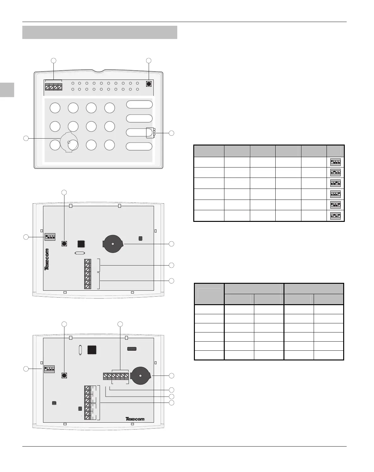
Installing Remote Keypads
Keypad Layouts
T
R
+
-
Premier RKP8/16 Plus Layout
Z1
COM
Z2
1
2
3
5
4
4 56
123
790
DISARM
BY
PASS
MENU
+
TR
-
8
AREA
1
ARM
STAY
24
3
Premier RKP4/8/16 Layout
Zone 1
T
A
Zone 2
T
A
NETWORK
+
TR
-
O/P-
Premier LCD/LCDL/LCDP/LCDLP Layout
1
2
3
5
4
6
SPK-
7
2 431
ON
2 431
ON
$
Address DIL Switch
%
Tamper Switch
&
Piezo Sounder
'
Data Bus Connections
(
Programmable Zones 1 and 2
)
Speaker Output (Premier LCDL/LCDLP Only)
*
Programmable Output
Remote Keypad Connections
The remote keypad is connected to the data bus terminals
located at the bottom left hand side of the PCB. (See pages
7 to 9).
Remote Keypad Address
Each remote keypad must be assigned a different address
using the Address DIL switch (
$
). The table below shows
how to set the address:
Address DIL 1 DIL 2 DIL 3 DIL 4
1 On/Off Off Off Off
2431
ON
2 Off On Off Off
2431
ON
3 Off Off On Off
2431
ON
4 Off Off Off On
2431
ON
5 On Off Off On
2431
ON
6 Off On Off On
2431
ON
Keypad Zones
The Premier RKP8/16 Plus and all LCD remote keypads have
two programmable zone inputs (see page 13 for wiring
details). Each zone is also fully programmable (see page 24
for programming details). The table below shows the zone
allocation when using the Premier RKP8/16 Plus or Premier
LCD remote keypads:
Premier 412 Premier 816/832
Address
Zone 1 Zone 2 Zone 1 Zone 2
1 Zone 05 Zone 06 Zone 09 Zone 10
2 Zone 07 Zone 08 Zone 11 Zone 12
3 Zone 09 Zone 10 Zone 13 Zone 14
4 Zone 11 Zone 12 Zone 15 Zone 16
5 N/A N/A N/A N/A
6 N/A N/A N/A N/A
!
The onboard remote keypad zones are not seen by
the system until they have been enabled. To enable
the onboard keypad zones (see page 41 for details).
Keypad Output
All Premier LCD remote keypads have one programmable
output, which can be used to drive auxiliary devices such as
LED’s, sounders or relays etc. Wire as per Panel Outputs
shown on page 18 (see page 46 for programming details).
 Loading...


