Premier 412/816/832 Installation Manual Installation
INS159 17
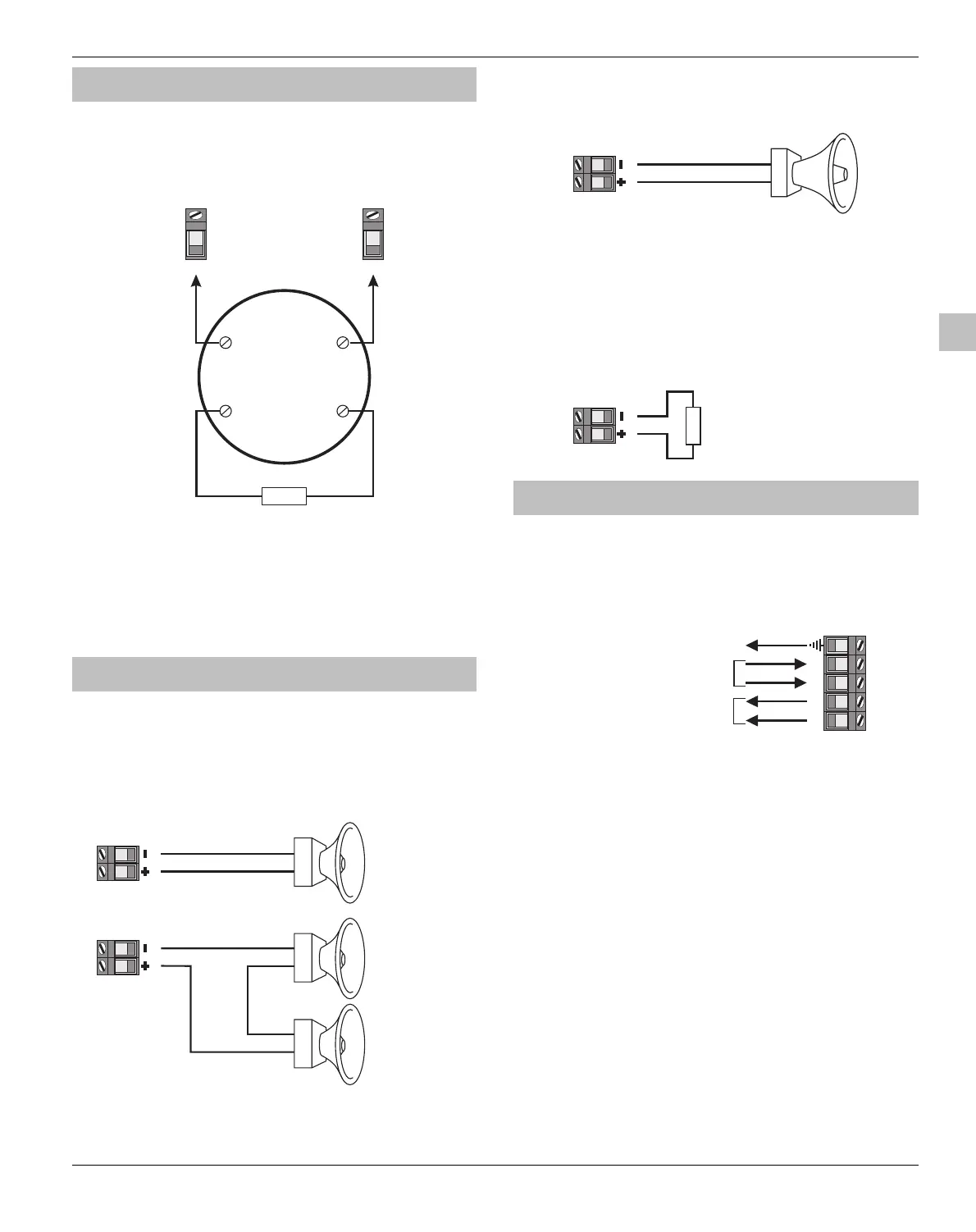
2-Wire Smoke Detector
Compatible 2-wire smoke detectors such as the ESL429AT
or System Sensor 2100TS can be connected as shown:
Output 1 Must be
Enabled for 2 Wire
Smoke Detectors
O/P 1
2-Wire
Smoke
Detector
Aux 12V +
E.O.L
1K
In In
Out Out
(+)
(+)
(-)
(-)
!
Panel Output 1 must be enabled for 2-wire smoke
detection (see page 35 for details).
The jumper link fitted across JP1 (Enabled 2-Wire
Smoke Det.) MUST be removed.
The maximum number of detectors is 20.
Speaker/Bell Connections
The Siren/Spk output terminals on the main PCB can be
configured for Speaker or Siren/Bell operation.
Speaker Operation
When configured as speaker operation the output can be
used for driving 8 or 16 Ohm loud speakers as shown:
Siren/Spk
8 Ohm Speaker
Siren/Spk
8 Ohm Speaker
8 Ohm Speaker
8W
8W
8W
!
The Siren/Spk output must be enabled for speaker
driver (see page 35 for details).
Siren/Bell Operation
When configured as bell operation the output terminals
provide up to 750mA of power for driving bells as shown:
Siren/Spk
Bell/Siren
+
-
The Siren/Spk output must be enabled for bell
driver (see page 35 for details).
Siren/Spk Supervision
The Siren/Spk output is supervised, if no warning devices
are fitted, either disable Siren Supervision (see page 36 for
details) or connect a 1KΩ resistor between the Siren
terminals as shown:
Siren/Spk
1K
if no warning devices are fitted,
connect a 1K resistor as shown.
Telephone Line Connections
The control panel has a built in digital communicator and
modem, which is used for communicating with an alarm
receiving centre and for downloading. If either of these
features are used, a telephone line must be connected to
the control panel as shown:
T R T1R1
In from telephone provider
Out to premises telephone
Connect to earth or an earth rod
Failure to fit an earth cable may prevent proper
operation of the system and will invalidate the
Texecom warranty and product approvals.
"
 Loading...


