Premier Elite 12-W/24-W/48-W Quick Start Guide
4 INS531-4
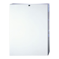
Control Panel
Mounting
Mount the control panel on a flat, plumb wall using at least three screws of
appropriate size.
It is essential to ensure that none of the fixing slots or cable entries
are accessible after fixing.
Mains cabling must be secured (e.g. with a cable tie) to one of the
anchor points provided.
Wiring the Control Panel
WARNING: ELECTRICITY CAN KILL
BEFORE connecting the control panel ALWAYS
disconnect the supply at the consumer unit.
If in ANY doubt consult a qualified electrician.
IMPORTANT SAFETY INFORMATION. HAZARDOUS VOLTAGES
INSIDE, NO USER SERVICEABLE PARTS, NO USER ACCESS.
ONLY connect the mains supply to the mains terminal
block, NEVER connect the mains supply directly to the
PCB.
ALWAYS refer to National Wiring Regulations when conducting
installation.
An appropriate and readily accessible disconnection device (e.g. an
unswitched fused spur) MUST be provided as part of the installation.
The disconnection device must NOT be fitted in a flexible cord.
Where identification of the neutral in the mains supply is NOT possible
a two-pole disconnection device MUST be used.
The building mains supply MUST incorporate appropriate short-circuit
backup protection (e.g. a fuse or circuit breaker) of High Breaking
Capacity (HBC, at least 1500A).
Use mains cable of adequate carrying capacity for the rated current
(i.e. at least 0.75mm
2
).
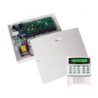
Control Panel Layout (
Premier Elite™
48-W Shown)
 Loading...
