Greenlee Textron / Subsidiary of Textron Inc.
5
4455 Boeing Dr., Rockford, IL 61109-2988 815/397-7070
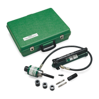
Hydraulic Punch Driver
1. Remove the dust caps from the couplers; attach the
hose to the ram and to the pump. Thread the dust
caps together.
Note: Hand-tighten the couplers completely until
all threads are engaged. Do not use tools.
2. Select the punch, die, and draw stud that will make
the appropriate size hole.
3. Determine and mark the exact location for the hole.
Using a drill bit that is slightly larger than the draw
stud, drill a hole. This is the
pilot hole
.
4. Thread the 3/4" piston shaft (B) completely into the
ram (A). See illustration.
Note: For a punch and die with a 3/8" center hole,
thread the 3/8" stainless steel adapter
screw (G) into the end of the piston shaft.
For a punch and die with a 1-1/8" center
hole, thread the screw sleeve (F) onto the
piston shaft.
5. Install spacers as necessary. See illustrations on
this page.
6. Slide the die over the draw stud with the open end
of the die facing away from the ram.
7. Insert the draw stud through the pilot hole.
8. Thread the punch onto the draw stud with the
cutting surfaces of the punch facing the material.
Tighten the punch by hand until the spacers, die,
material, and punch are snug.
Note: If the ram stops before the hole is complete,
stop pumping. Check that the setup is
correct and that you have not exceeded the
tool’s capacity. See the setup instructions.
If necessary, disassemble the setup and
add a spacer.
9. Activate the pump. For specific instructions, see the
operating manual supplied with the pump.
Note: Support the weight of the ram when
operating the pump. This will prevent the
ram from falling when the punch is
complete.
10. Release the pressure at the pump.
PUNCH
1-1/8" SLEEVE
PUNCH
DIE 3/8" DRAW STUD 3 SPACERS
3/4" DRAW STUD
RAM
DIE
MATERIAL
PUNCH DIE SPACER
AS NEEDED
MATERIAL
MATERIAL
Note: All of the punch threads must be engaged
by the draw stud threads. If any of the
punch threads are not engaged, dis-
assemble the setup, remove one of the
spacers and reassemble the setup.
Setup and Operation
Completed Assembly
Do not operate the pump after ram motion stops.
Continuing to operate the pump lever after the
ram stops will damage the ram.