Always adjust the receiver sensitivity for a less than full scale reading and
correlate the transmitter beep with the receiver meter indication.
6. Move the “A” Frame in line with and down the faulted conductor path.
Be sure to insert the “A” Frame probes deeply enough to insure good
ground connection. Strongest indications will be present at the transmitter
and at the fault. If the signal begins to fall off or decrease in strength while
probing down the faulted conductor path, continue until it comes back up
again.
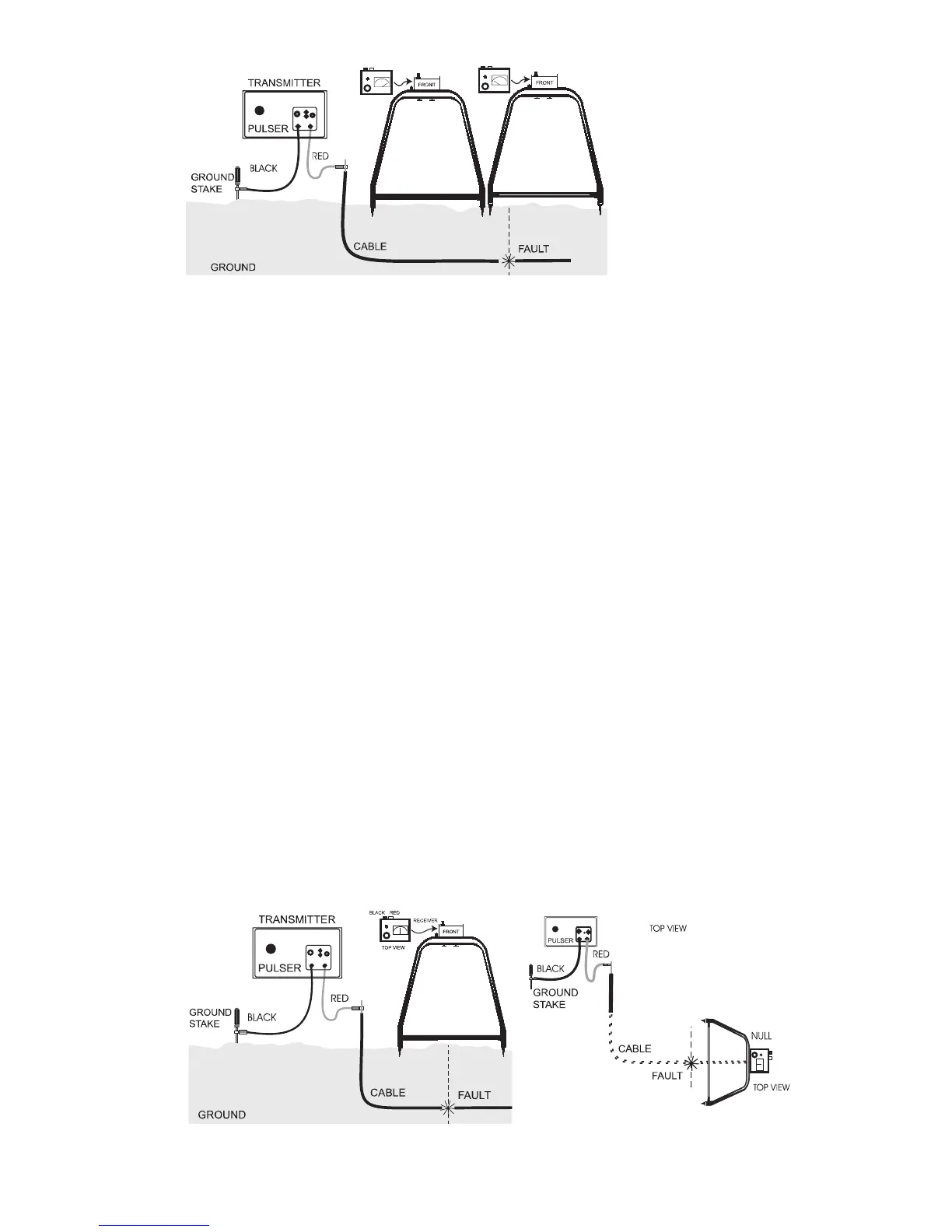
7. While probing the path, a reversal in the receiver meter, a “black” kick, will
be observed when the fault is passed.
To determine the exact location, move the “A” Frame in the direction of the
black kick until the kick reverses to red. (See Figure 3.) Now move the “A”
Frame in small increments back to the red kick until it reverses to a black
kick or it nulls. (See Figure 4.)
Note: Receiver will null when probes evenly straddle the fault. Mark this
spot. (See Figure 5.)
8. Insert the “A” Frame at right angles or perpendicular to the cable path,
through the point of the first null. Repeat the procedure outlined in 2.7 until
a second null occurs.
Note: Receiver will null when probes evenly straddle the fault. Mark this
spot. (See Figures 4 and 5.)
5
Figure 3.
Probing Cable Path –
Reversal
Figure 4. Nulling Receiver – First Time
Figure 5. Nulling Receiver –
Second Time