B5
B2
B6
A10
B4
A10
A10
B5
A10
B2
2
1
3
C3
P18
P13
C8
C5
3
2
1
4
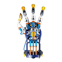
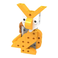
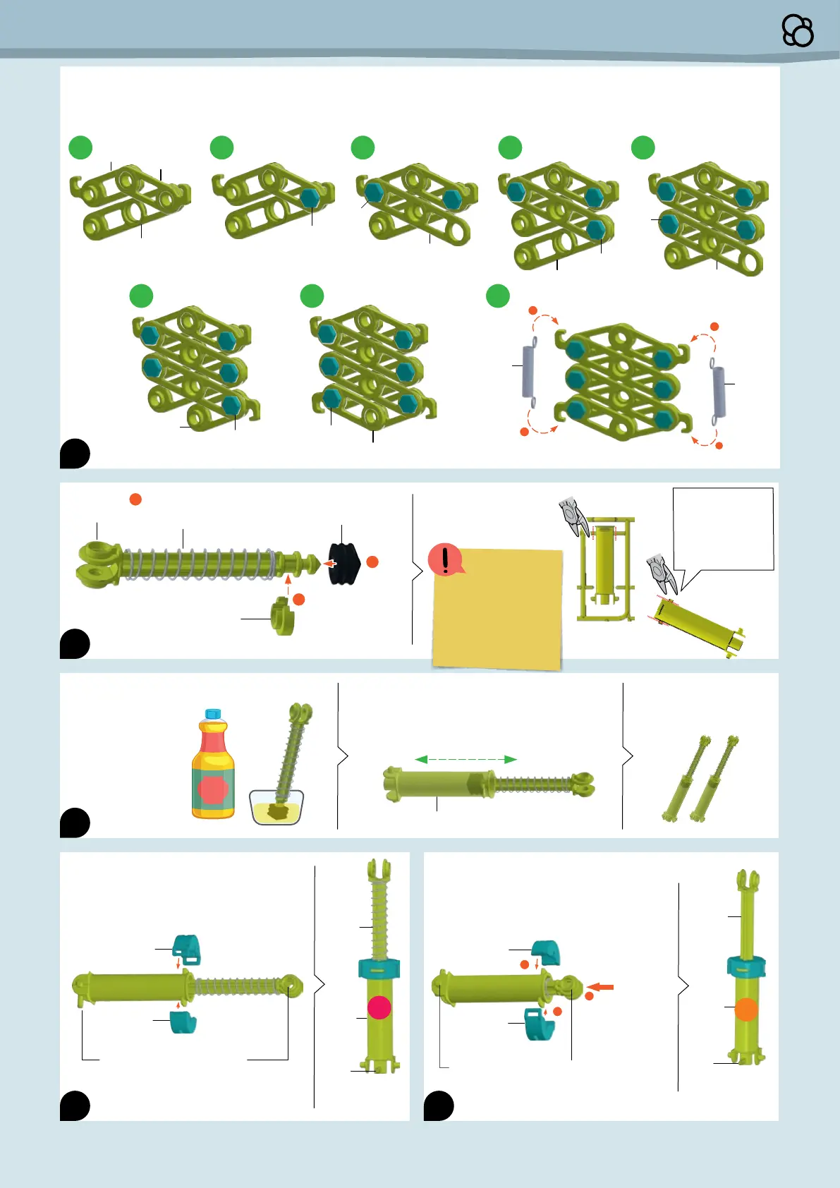
Assemble the scissor arm mechanism. Lay
the parts flat on a table. These images show
the parts viewed from above.
1 2 3 4 5
6 7 8
A10
B6
A10
B4
P19
P19
Note: When inserting A10, pick up the parts with
both hands. Make sure the parts are fastened
together before moving on to the next step.
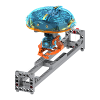
Add the spring (P18) to C5.
Insert the piston from step 12 into the
hydraulic cylinder (C8) and move it back and
forth several times to coat the inside of the
cylinder with oil. Reapply oil as necessary.
A12
A13
With the first cylinder, make sure the
spring (P18) is completely outside of the
cap (A12 + A13).
Note the hole’s orientation
relative to the nozzle.
Piston
Cylinder
Nozzle
A13
After the part is
removed from the
frame, remove
the burrs with the
diagonal cutters.
A12
H2
1
2
2
With the second cylinder, make sure the
spring (P18) is completely inside of the
cap (A12 + A13).
Note the hole’s orientation
relative to the nozzle.
Push the
piston all
the way
in before
placing
the cap.
Piston
Cylinder
Nozzle
After adding the
spring, press C3
onto C5 here.
Carefully remove C8
from the plastic frame
and set aside.
Pour vegetable oil
into a small bowl.
Then dunk the
piston seal (P13)
into the oil, making
sure to coat it
completely.
Repeat steps 12 and
13. You will end up
with two hydraulic
cylinders:
You have made
hydraulic 1 (H1).
You have made
hydraulic 2 (H2).
H1
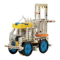
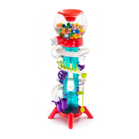
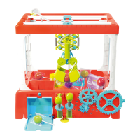
Assembling the Candy Claw Machine
5
The tabs on 8 are
thcker and must be
cut lttle by lttle, and
as far away from the
part as possble
 Loading...