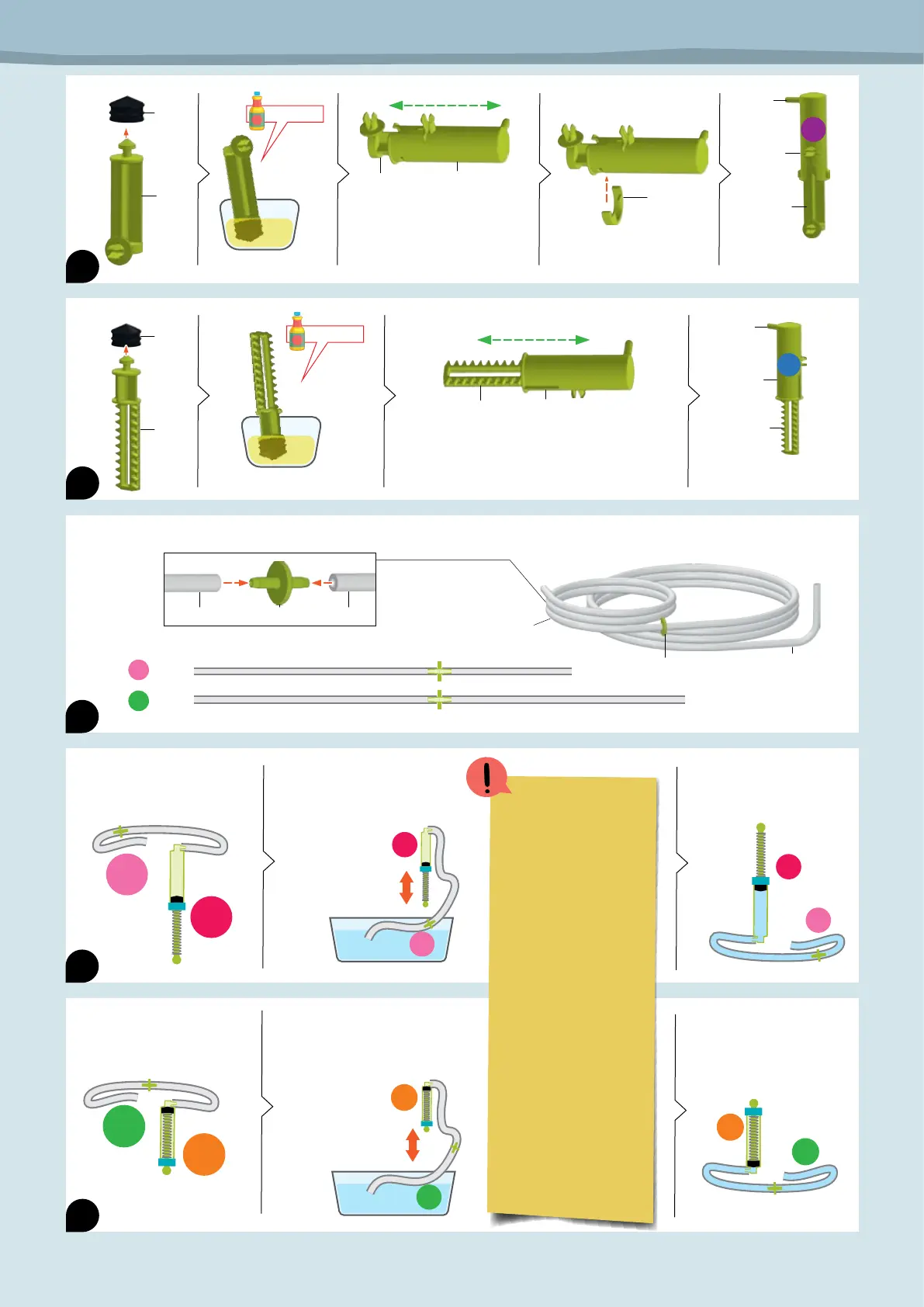
6
Submerge the loose end of T1
in the basin of water. Orient
the nozzle of H1 toward the
top, then move
the piston up
and down until
H1 and T1 are
filled with water.
Water will remain in
the cylinder and tube.
Set aside.
Connect the long end of
tube T1 to the nozzle of H1.
Connect the tube T2 to
the nozzle of H2.
Submerge the loose end of T2
in the basin of water. Orient
the nozzle of H2 toward the
top, then move
the piston up
and down until
the tube and the
top of H2 are filled
with water.
Let the spring draw the
piston back into the
cylinder. Water will remain
in the tube. Set aside.
You have made
hydraulic 3 (H3).
You have made
hydraulic 4 (H4).
C12
P16
P16
C6
C11
C12 P16P16
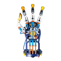
Tube assembly: There are three 450-mm tubes and one 240-mm tube. Connect them as shown here.
Piston
Cylinder
Nozzle
Piston
Cylinder
Nozzle
H3
240 mm
Tube 2
450 mm
T2
Tube 1
450 mm450 mm
T1
Lubricate P13!
P13
P13
Lubricate P13!
C6
C4
C11
C7
Move C6 back and forth
several times to coat the
inside of the cylinder (C4) with
oil. Reapply oil as necessary.
C2
Move C11 back and forth several
times to coat the inside of the cylinder
with oil. Reapply oil as necessary.
H4
T1
H1
T1
H1
H2
T2
H2
T2
T1
H2
T2
H1
Watch for leaks as
you fll the cylnders
Only water should be
fllng the cylnder
If you see ar fllng
the cylnder, try the
followng
1 arefully remove
the cap (A12 and
A13) and re-ol the
pston
2 heck for cracks n
the tube (8)
3 heck for tears
n the pston seal
(P13)
If any part s
damaged, contact
techncal support for
a replacement
 Loading...