EasyManua.ls Logo

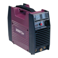
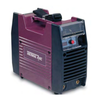
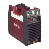
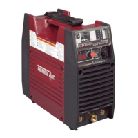
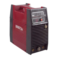
Thermal Arc ARCMASTER 200 TS User Manual

Thermal Arc ARCMASTER 200 TS
96 pages
To Next Page IconTo Next Page
Page #1 background imageLoading...
Page #1 background image
INVERTER ARC WELDER
Revision No: AB Issue Date: May 7, 2008 Manual No.: 0-4941B
Operating Features:
200 TS
Service Manual
Art # A-06912
ARCMASTER
®

Table of Contents

Question and Answer IconNeed help?

Do you have a question about the Thermal Arc ARCMASTER 200 TS and is the answer not in the manual?

Thermal Arc ARCMASTER 200 TS Specifications

General IconGeneral
Input Voltage230 V
Input Frequency50/60 Hz
Rated Input Current16 A
Output Current Range (TIG)10 - 200 A
Duty Cycle (TIG)60% at 200 A
Duty Cycle (MMA)60% at 200 A
Input PhaseSingle Phase
Rated Output200 A

Summary

SAFETY INSTRUCTIONS AND WARNINGS

Arc Welding Hazards and Electrical Safety

Details electrical shock, arc ray hazards, and safety measures.

Fumes, Gases, and Fire Safety

Covers hazardous fumes, gases, fire/explosion risks from welding.

INTRODUCTION

How To Use This Manual

Explains manual structure, annotations (WARNING, CAUTION, NOTE), and how to get more copies.

INSTALLATION

Electrical Input Requirements

Details the single-phase AC power supply requirements.

Electrical Input Connections

Procedures for safely connecting the welder to the power supply.

Input Power and Power Supply Details

Explains the inrush circuit, voltage sensing, and generator use for input power.

Duty Cycle Explanation

Defines duty cycle and its impact on welder operation and potential damage.

OPERATOR CONTROL

Control Panel Overview

Identifies and describes the front panel controls, including the digital meter and knob.

Weld Process Selection

Explains how to select different welding processes (STICK, MIG, TIG) and modes.

Weld Parameter Descriptions

Details the function of each adjustable parameter on the front panel.

Weld Parameters and Settings

Lists the available weld parameters, their ranges, factory settings, and applicable weld modes.

SET-UP FOR SMAW (STICK) AND GTAW (TIG)

SEQUENCE OF OPERATION

Stick Welding Sequence

Step-by-step guide for setting up and performing stick welding.

TIG Welding Sequences (HF & Lift)

Instructions for setting up and performing HF TIG and Lift TIG welding.

BASIC TROUBLESHOOTING

TIG Welding Problems and Solutions

Lists common TIG welding quality issues and their causes/remedies.

Stick Welding Problems and Solutions

Identifies common stick welding defects and provides troubleshooting steps.

Power Source Problems and Solutions

Troubleshooting guide for common power source operational failures.

VOLTAGE REDUCTION DEVICE (VRD)

POWER SOURCE ERROR CODE

Error Code Descriptions and Remedies

Explains common error codes displayed by the power source and provides troubleshooting steps.

ADVANCED TROUBLESHOOTING

System-Level Fault Isolation and Enclosure Opening

Guides on isolating faults to subsystems and safely opening the unit.

Error Code Verification and Remedy

Procedures for verifying and resolving specific error codes (E01, E02, E03, E94, E99).

Troubleshooting Failures Without Error Codes

Steps for issues not indicated by codes (fan, gas valve).

No Weld Output and Panel Failure Diagnosis

Troubleshooting steps for no weld output and operating panel failures.

High Frequency Output Failure Diagnosis

Steps to troubleshoot when the unit does not generate High Frequency output.

Fault Isolation Tests and Preparation

Initial conditions and preparation steps for performing fault isolation tests.

Power Input Circuitry Verification

Steps to verify AC input voltage.

MAINTENANCE

APPENDIX 3 INTERCONNECT DIAGRAM

Related product manuals